D-MBR 3707-3708 PS NFPA CLASS A SIGNAL BOOSTER
PRODUCT DESCRIPTION AND USER’S MANUAL
www.cobham.com/wireless
Date: 17-Jan-16
Cobham Wireless – Coverage
Page | 4 Rev. 1.1 Doc. No.00060CDUM
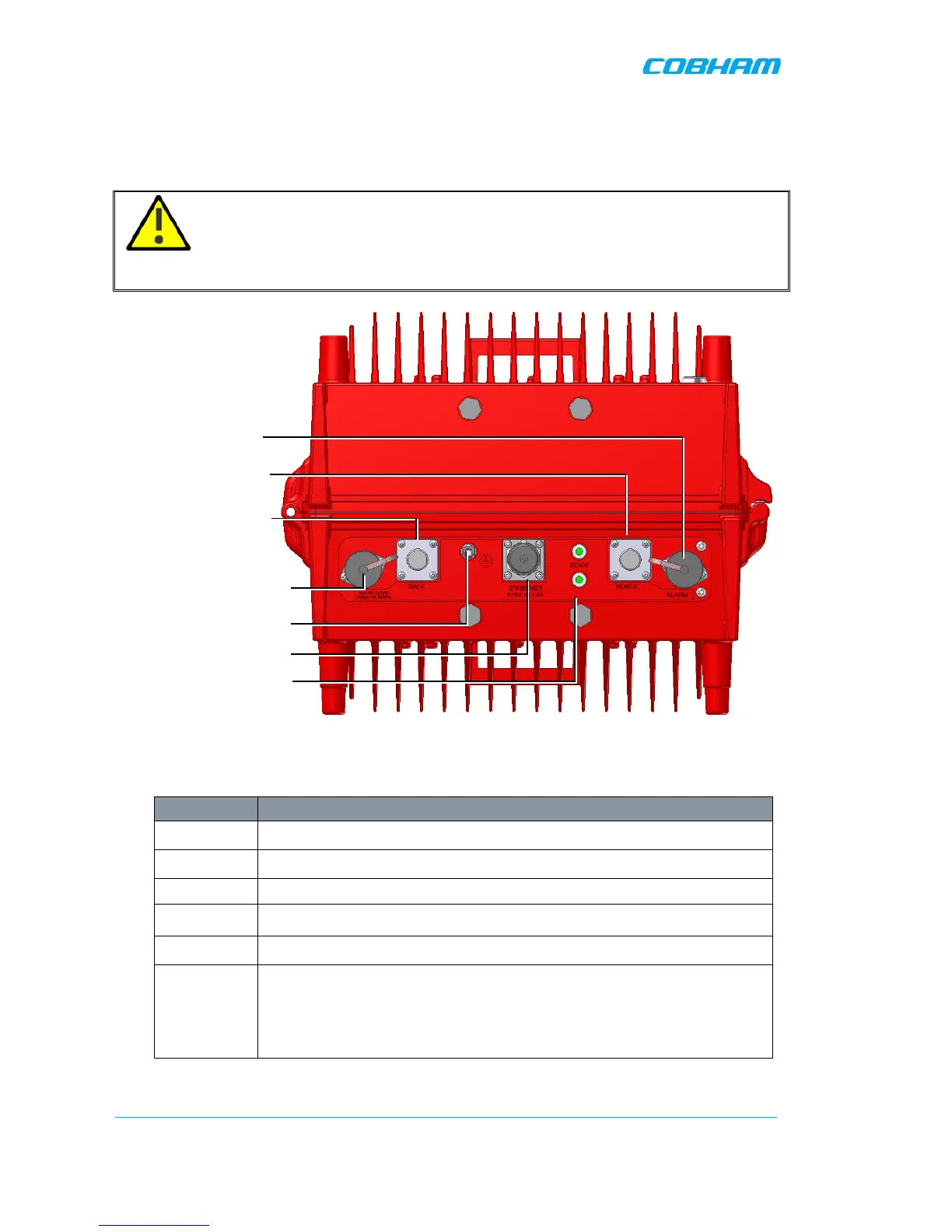
1.6 Booster Interfaces
All booster interfaces are located on the underside as shown below.
WARNING! The signal booster must always be installed vertically and top-down – with
the connectors on the underside for protection (see 3.3.3.4). Horizontal installation on a bench for
long time may cause damage to the signal booster due to over-heating.
Figure 1-3. D-MBR Front Panel
Interface Description
BASE
Donor antenna connections. See section
2.1.
MOBILE
Service antenna connections. See section
2.2.
48 VDC Connection to 48VDC (either from UPS or from the Charger).
ALARMS
Two External (input) and two Output (relay) alarms. See section
3.4.3.
GND LUG
Ground connection. See section
3.4.1.
LED’S Two status LEDs: 700 MHz and 800 MHz bands
Upper LED: UL status (for both bands.
Lower LED: DL status for both bands
Status: Green (OK), Orange (Warning), Red (Fail).