D-MBR 3707-3708 PS NFPA CLASS A SIGNAL BOOSTER
PRODUCT DESCRIPTION AND USER’S MANUAL
Cobham Wireless – Coverage
Date: 17-Jan-16
www.cobham.com/wireless
Doc. No.00060CDUM Rev. 1.1 Page | 5
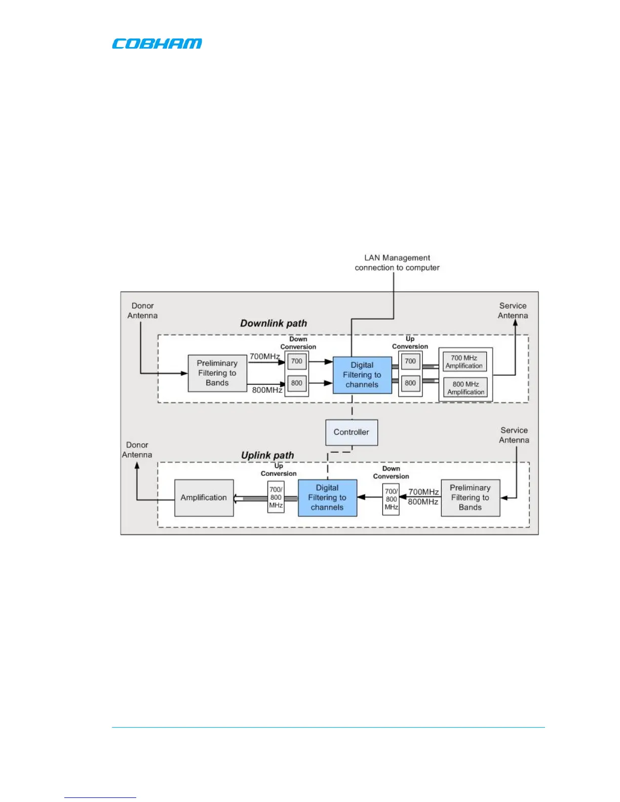
1.7 Functional Description
In the downlink, the signal from the Donor antenna is filtered to the 700MHz and 800MHz bands,
down converted, filtered according to the user defined (via GUI) channels, down converted and
amplified. The signals are then forwarded to the service antenna. In the uplink, the process is
reversed.
The maximum Analog Gain is 95dB, where Channel Gain between 0dB and 95dB is achieved by
reducing the Digital Gain from the System maximum Analog Gain; therefore, filtering and attenuation
is achieved through Digital Processing.
The block diagram showed in the figure below illustrates the overall functionality of the D-MBR PS
NFPA Signal Boosters and shows the operation flow in the downlink path and the uplink path.
Figure 1-4 Signal Booster - Block Diagram