D-MBR 3707-3708 PS NFPA CLASS A SIGNAL BOOSTER
PRODUCT DESCRIPTION AND USER’S MANUAL
Cobham Wireless – Coverage
Date: 17-Jan-16
www.cobham.com/wireless
Doc. No.00060CDUM Rev. 1.1 Page | 23
3.4 Booster Connections
NOTE: The Charger connections are described in the following section.
This section describes the Booster connections:
• Grounding
• Antenna connections
• Power-up
3.4.1 Grounding
NOTE: The grounding procedure is identical for both BOOSTER and BATTERY CHARGER.
3.4.1.1 Grounding Wire Requirements
Requirements for grounding wires
• Protective grounding conductor - should be aluminum with cross-section 10AWG.
• Lug of the protective grounding conductor - should be aluminum
• Washers and screw - should be high Cr stainless steel, or 12% Cr stainless steel, or Cr on, Ni on
steel, tin on steel
3.4.1.2 Grounding Units
WARNING!! Ground the Signal Booster with the booster’s grounding bolt. Do not use the
grounding bolt to connect external devices.
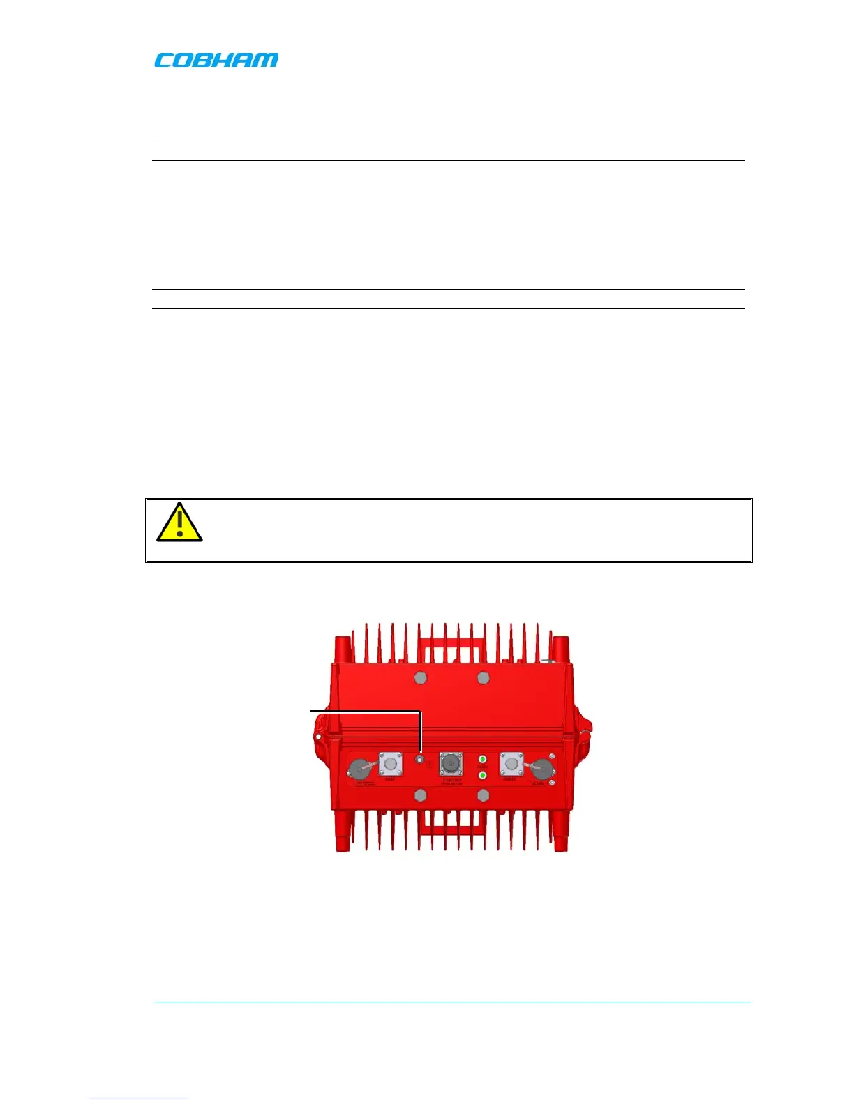
Connect the grounding wire to the GND lug on each unit as shown below.
Figure 3-15 Booster GND Lug
GND LUG