D-MBR 3707-3708 PS NFPA CLASS A SIGNAL BOOSTER
PRODUCT DESCRIPTION AND USER’S MANUAL
Cobham Wireless – Coverage
Date: 17-Jan-16
www.cobham.com/wireless
Doc. No.00060CDUM Rev. 1.1 Page | 35
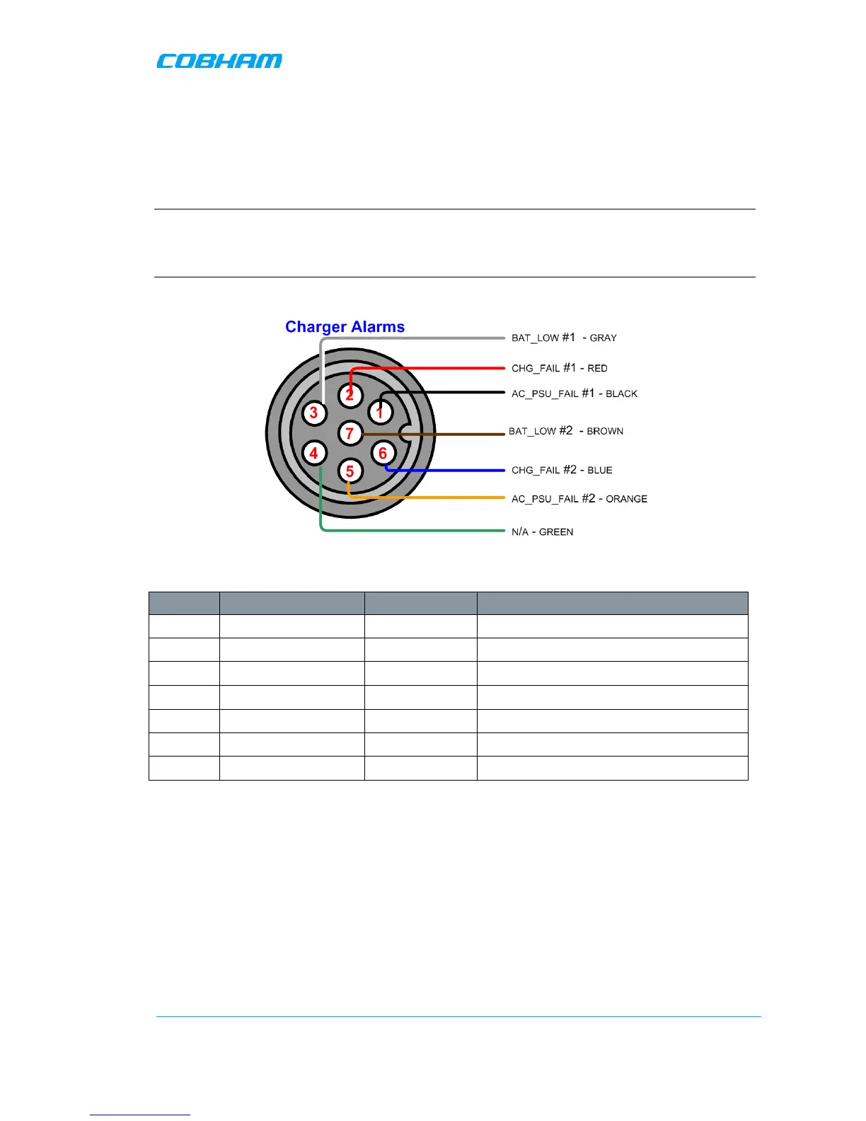
4.4.5.3 Charger Alarm Connector Pinout
Each alarm status is recognized by a separate wire-pair, where the colored wires are internally
connected with a 4.7 K ohm resistor (serves as a pull up resistor to +5V. The following figure shows
the Alarm connector pinout.
NOTE: SNMP alarm notification can be provided for ONE of these alarms. This is done by connecting
the alarm to the Booster External Alarm Connector, Ext Alarm IN 1 (section 3.4.3.3). It is then
required to configure External Alarms 1 as Normal High and name the alarm (section 5.5). (To
disable the alarm notification, set the alarm as Low. Default from production: AC PWR FAIL.
Figure 4-7. Charger Alarm Connector Pinout
Pin No. Signal Name Wire Colour Contact Type and description
1 AC_PSU_FAIL #1 Black dry-contact NC
2 CHG_FAIL #1 Red Dry-contact NC
3 BAT_LOW #1 Gray dry-contact NC
4 N/A Green dry-contact NC
5 AC_PSU_FAIL #2 Orange dry-contact NC
6 CHG_FAIL #2 Blue dry-contact NC
7 BAT_LOW #2 Brown dry-contact NC
 Loading...