OPTICAL MASTER UNIT MARK I
PRODUCT DESCRIPTION AND USER’S MANUAL
Cobham Wireless – Coverage Date: 4-Jan-18 www.cobham.com/wireless
Document number:A1829300UM Rev. 3.1
Page | 5
1.4 OMU Modules
The OMU is a rack type casing designed for a 19” sub-rack. The chassis supports up to six F/O to RF
converters, in addition to Control, Power, Modem and additional required interface units.
Each of the modules is described in detail in the following sections.
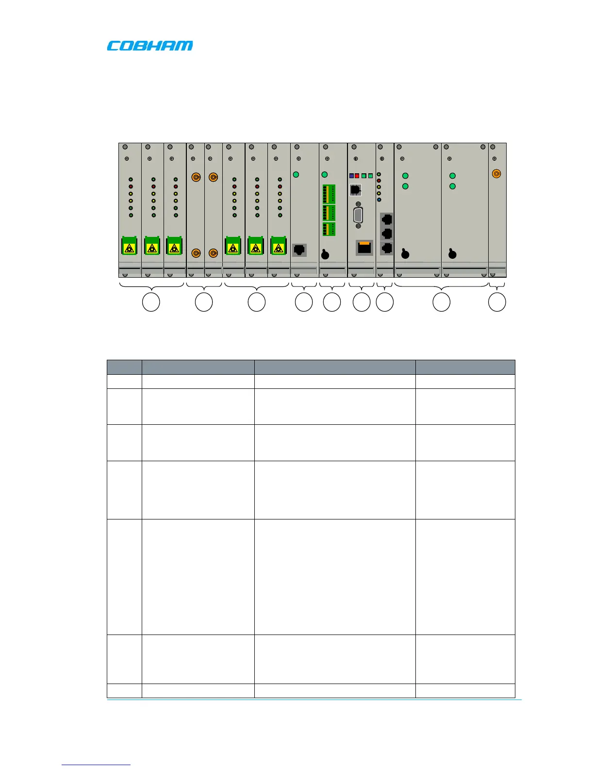
Figure 1-5. OMU Front Panel Interfaces
An OMU unit can contain the following modules:
Label Unit Description Allocated Slots
1. Fibre Optic Converter Up to 6 WDM optic converters 1, 2, 3 and 6, 7, 8
2. UL Combiner and DL
Splitter
Combine and distribute the RF
signals between the OMU’s RF port
and the Fibre Optic Converters.
4 and 5 respectively
3. Modem Optional. This unit is used for
modems that are not mounted on
the Control Module.
9
4. External Alarm and
Battery Module.
Supports 4 dry-contact alarms, 1
relay, and a battery (can be turned
off) that enables the modem to
transmit am alarm in case of loss of
input power.
10
5. Control Module Relevant only for Master OMU 9 or 11 – without an
integrated wireless
modem (mounted on
the control module).
11 only – if the
module includes a
wireless modem (to
be near modem
antenna module –
slot 14).
6. Rack communication
board
Provides communications link
between the Control Module and the
Fiber Optic Converters.
Also used when cascading OMUs.
12
7. Power Supply modules (A PS B is optional for redundancy 13