EasyManuals Logo

COBHAM OMU I User Manual

COBHAM OMU I
60 pages
To Next Page IconTo Next Page
To Previous Page IconTo Previous Page
Page #24 background imageLoading...
Page #24 background image
OPTICAL MASTER UNIT MARK I
PRODUCT DESCRIPTION AND USER’S MANUAL
Cobham Wireless Coverage Date: 4-Jan-18 www.cobham.com/wireless
Document number:A1829300UM Rev. 3.1
Page | 18
2.6 OMU Module Configuration Examples
An OMU can be configured in many different ways. These are two examples.
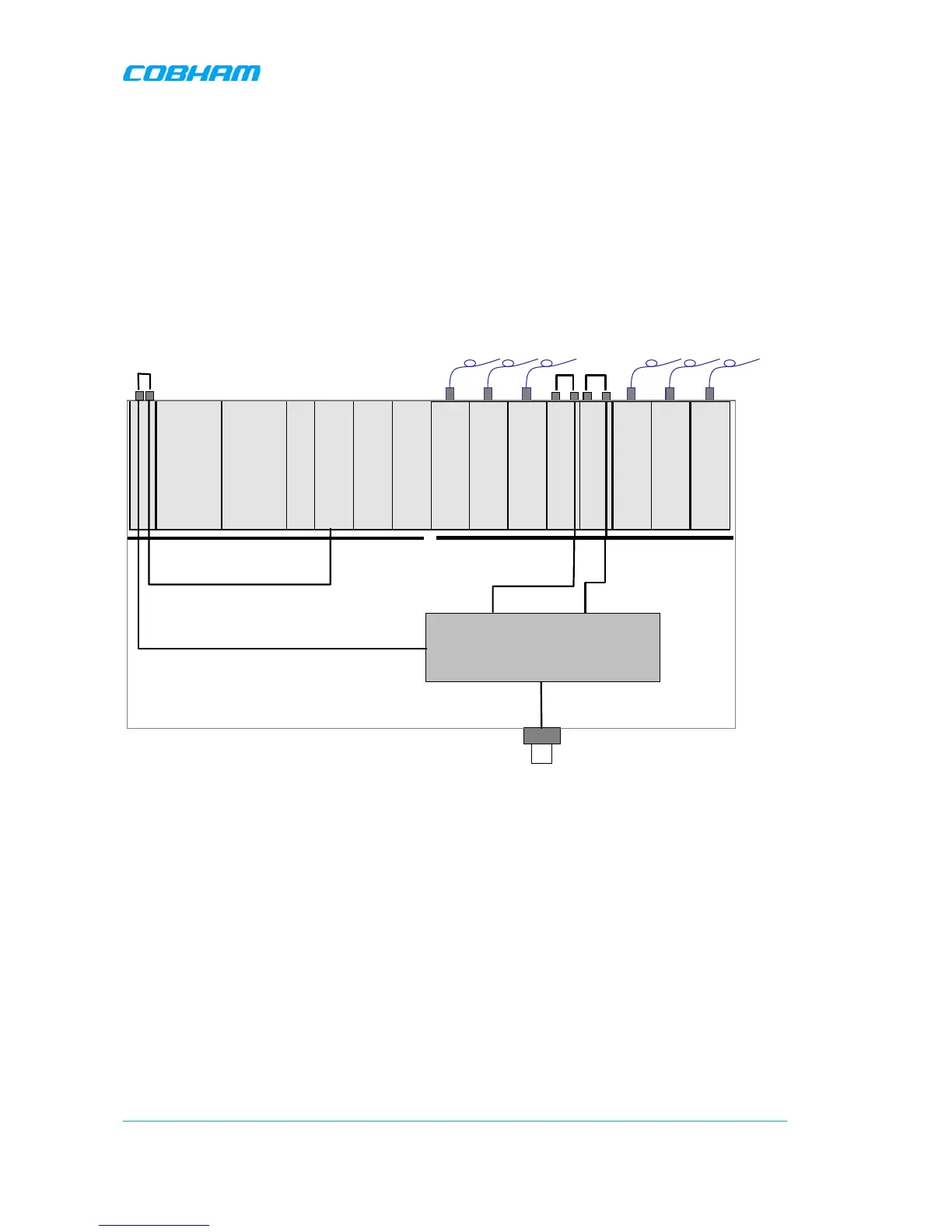
Example 1
In this example the OMU is fed from the back so the links on the UL Combiner and the DL Splitter
units are mounted.
There is a duplex filter and therefore a combined RF in/out.
The wireless modem, which is placed on the Control Module, is connected to the coupler in the filter
via the Modem Antenna Connection Module.
RF Backplane
Opto
Module
RF
IN
RF
OUT
Control Module
External Alarm and
Battery Module
Rack Com Board
Power
Module B
Power
Module A
Digital Backplane
RF in/out
Duplex Filter
DL Splitter
UL Combiner
Opto
Module
RF
IN
RF
OUT
Opto
Module
RF
IN
RF
OUT
Opto
Module
Opto
Module
RF
IN
RF
OUT
Opto
Module
RF
IN
RF
OUT
Opto
Module
RF
IN
RF
OUT
To coupler for
modem antenna

Table of Contents

Questions and Answers:

Question and Answer IconNeed help?

Do you have a question about the COBHAM OMU I and is the answer not in the manual?

COBHAM OMU I Specifications

General IconGeneral
BrandCOBHAM
ModelOMU I
CategoryNetwork Hardware
LanguageEnglish