OPTICAL MASTER UNIT MARK I
PRODUCT DESCRIPTION AND USER’S MANUAL
Cobham Wireless – Coverage Date: 4-Jan-18 www.cobham.com/wireless
Document number:A1829300UM Rev. 3.1
Page | 25
Baud rate The default value changes when the controller
type is selected. (Other values are also available
for specific
manual.)
Slot Assignment Click the button that corresponds to the fibre
optic converter the repeater is connected to.
NOTE: To confirm an installation or to check the
present configuration select a fibre optic converter and
click the button
.
If a
repeater is installed in this position the repeater serial
number will be presented.
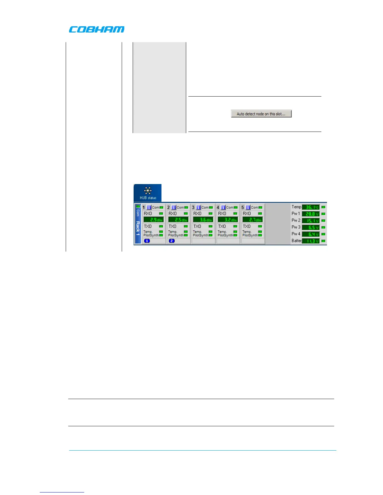
Check the LEDs on
Converters
The Fiber Optic Converter contains two optical alarm sources. These are
alarms for transmitted and received optical signal level.
Select HUB Status
the RMC
3.8 Balance the System
To estimate the signal levels in the system, a link budget should be prepared before the system is
made
operational. This section provides background on calculating the required attenuation values along
the link and
describes how to set the attenuation value in the management application.
3.8.1 Downlink Path
The following two diagrams illustrate the attenuation levels for two types of installations:
• BS with separate Tx and Rx ports – for a total attenuation of 44dB (attenuator set to 0)
• BS with a common Tx and Rx port – for a total attenuation of 45dB (attenuator set to 0)
Also note the following:
• Any additional required attenuation (up to -21dB) is implemented via the Variable Attenuator.
• The input level to the laser should be ≤-3dBm composite power
NOTE: As the composite power in a multicarrier TETRA/TDMA/W-CDMA/LTE system is traffic dependent, the
maximum laser input power must be calculated for the traffic scenario that will require highest composite power.
After the downlink attenuation been set, the gain of the connected repeaters should be adjusted individually in
accordance to the relevant section in the manual for each repeater connected to the OMU.
The following diagram illustrates the attenuation levels for an installation with separate Tx and Rx
ports.
 Loading...