OPTICAL MASTER UNIT MARK I
PRODUCT DESCRIPTION AND USER’S MANUAL
Cobham Wireless – Coverage Date: 4-Jan-18 www.cobham.com/wireless
Document number:A1829300UM Rev. 3.1
Page | 26
Fiber Fed
Repeater
e
o
OMU
BTS
Directional
Couplers (x2)
Loss in fiber
cable
10 Km
Variable
Attenuator
-14 dB
-30 dB
BTS Output
up to
- 21 dB
Variable
Attenuator
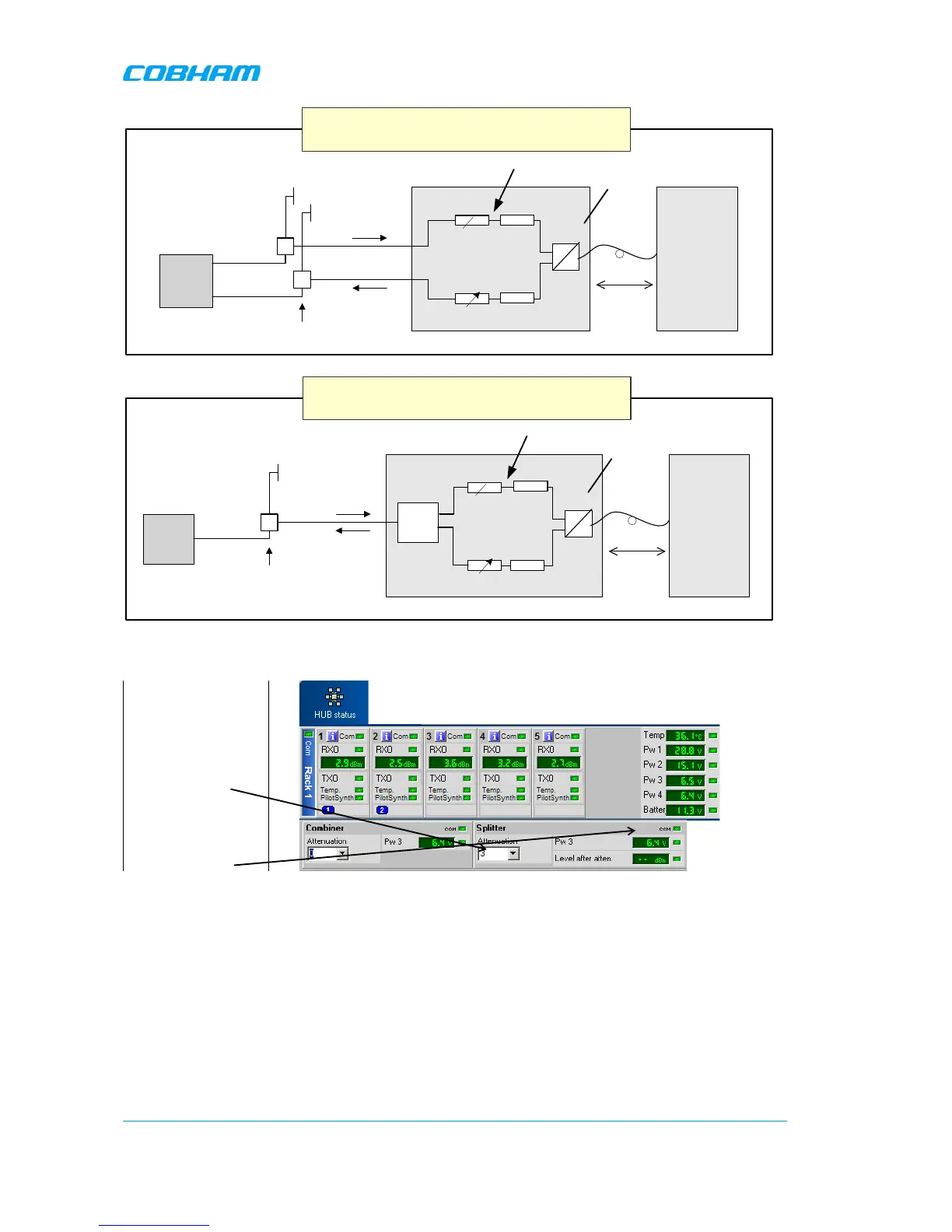
Basic Explanation of Attenuation Levels for BS with
SEPARATE Tx and Rx ports
up to
- 21 dB
-14 dB
Total attenuation = 44dB
Recommended power = -3dBm
RX
TX
-30 dB
BTS Input
Splitter
Measured Power
Combiner
The following diagram illustrates the attenuation levels for an installation with a common Tx and Rx port.
Fiber Fed
Repeater
Duplex
Filter
e
o
OMU
BTS
Loss in fiber
cable
10 Km
Variable
Attenuator
- 1 dB
up to
- 21 dB
Variable
Attenuator
Basic Explanation of Attenuation Levels for BS
with COMMON Tx and Rx ports
up to
- 21 dB
- 14 dB
Total attenuation = 45dB
Recommended power = -3dBm
BTS Output
RX/TX
-30 dB
Directional
Coupler
Splitter
Measured Power
- 14 dB
Combiner
To set the attenuation
Select “HUB Status”
Set the attenuation in
the downlink in this
box.
The signal level after
attenuation can be
monitored in the RMC
3.8.2 Fiber Loss Compensation
Activate the fibre loss compensation in both the downlink (from the OMU) and in the uplink (from the
repeaters) paths. See
3.9 Initiate Fibre Loss Compensation.