OPTICAL MASTER UNIT MARK I
PRODUCT DESCRIPTION AND USER’S MANUAL
Cobham Wireless – Coverage Date: 4-Jan-18 www.cobham.com/wireless
Document number:A1829300UM Rev. 3.1
Page | 9
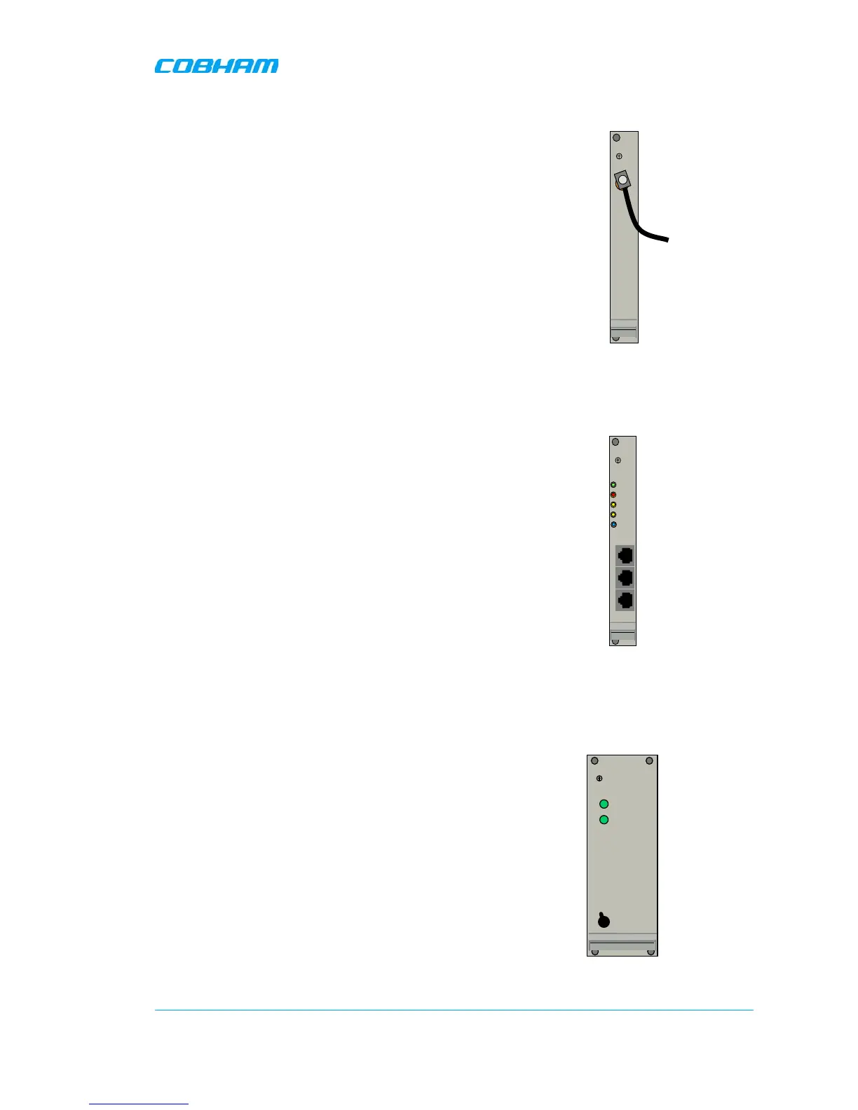
1.4.7 Modem Antenna
This module performs the following functions:
• Relevant only if a wireless modem is installed in the
OMU
• Provides the connection to an external (modem)
antenna
Figure
1-12.Modem Antenna
1.4.8 Rack Communication Board
This module performs the following functions:
• Provides communications link between the Control
Module and the Fiber Optic Converters within the
rack.
• Provides communication between cascaded OMUs.
• LEDs indicate communication status between Control
Module and F/O converters.
Figure
1-13. Rack Communication
Board
1.4.9 Power Supplies
This module performs the following functions:
• Two independent power supply modules with ON/OFF
switches:
115 - 230VAC 50/60 Hz and 24 - 48VDC.
• LEDs indicating normal levels of input and output
voltages
• Each Power Supply can be switched off using the
ON/OFF switches on the front panel.
ATTENTION!
The power source is connected at the
REAR of the unit. Even when the power supplies are
switched off the OMU still has live power from the
power input on the rear.
Modem
ANT
To external
antenna
ERR
PWR
UL
DATA
DL
DATA
Link OK
IN OUT 1
OUT 2
ERR
PWR
UL
DATA
DL
DATA
Link OK
IN OUT 1
OUT 2