OPTICAL MASTER UNIT MARK I
PRODUCT DESCRIPTION AND USER’S MANUAL
Cobham Wireless – Coverage Date: 4-Jan-18 www.cobham.com/wireless
Document number:A1829300UM Rev. 3.1
Page | 27
3.8.3 Uplink Path
The uplink gain setting of the OMU and connected repeaters affects the sensitivity in the connected
BTS sector and the connected repeater cells. The recommended method for setting up the system
below will give good noise performance in simple systems with a relative low number (less than six)
of connected repeaters per BTS sector.
For more complex systems, with many repeaters connected to the same BTS sector using multi-drop,
a more detailed system analysis is required to set up the system in an optimum way.
• Set the uplink attenuation in the OMU equal to the downlink attenuation.
• Set the uplink gain of each connected repeater equal to the downlink gain of the repeater (by
setting the attenuation value in the RMC for both links equal).
3.8.4 Noise Considerations
To reduce the noise degradation of the base station, it is recommended to reduce repeater uplink
gain only. The repeater cells will in this case not be perfectly balanced, i.e. downlink can take higher
path loss than uplink. In typical systems where you want to cover for example a road tunnel by
tapping off a BTS nearby this small imbalance is less of a problem.
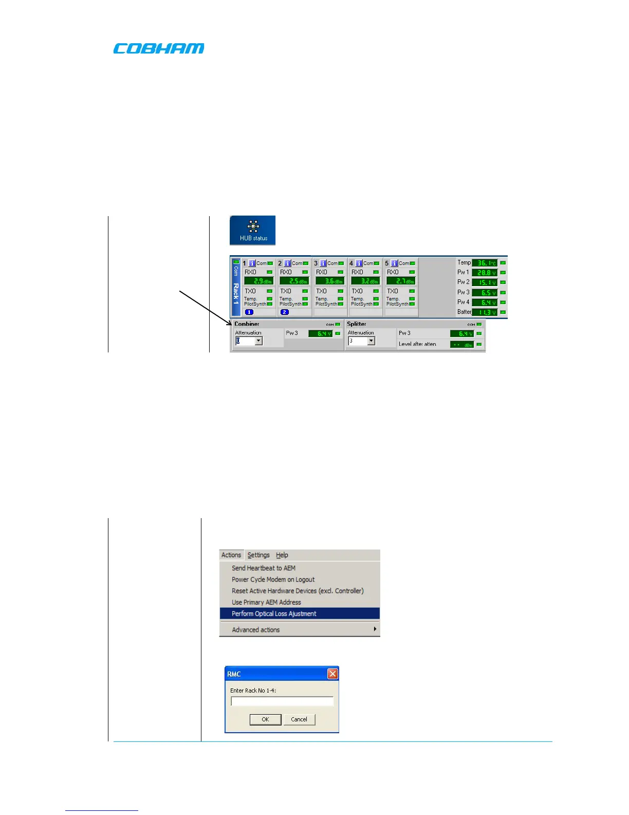
3.9 Initiate Fibre Loss Compensation
See section 3.3 Fiber Loss Compensation for information about this feature.
Start with the OMU
Choose “Actions/Perform Optical Loss Adjustment” from th
In an OMU that contains only one sub
rack – this rack is called “Rack 1”
Additional sub-racks/slave OMUs that