OPTICAL MASTER UNIT MARK I
PRODUCT DESCRIPTION AND USER’S MANUAL
Cobham Wireless – Coverage Date: 4-Jan-18 www.cobham.com/wireless
Document number:A1829300UM Rev. 3.1
Page | 45
4 TROUBLESHOOTING
4.1 Module LEDs
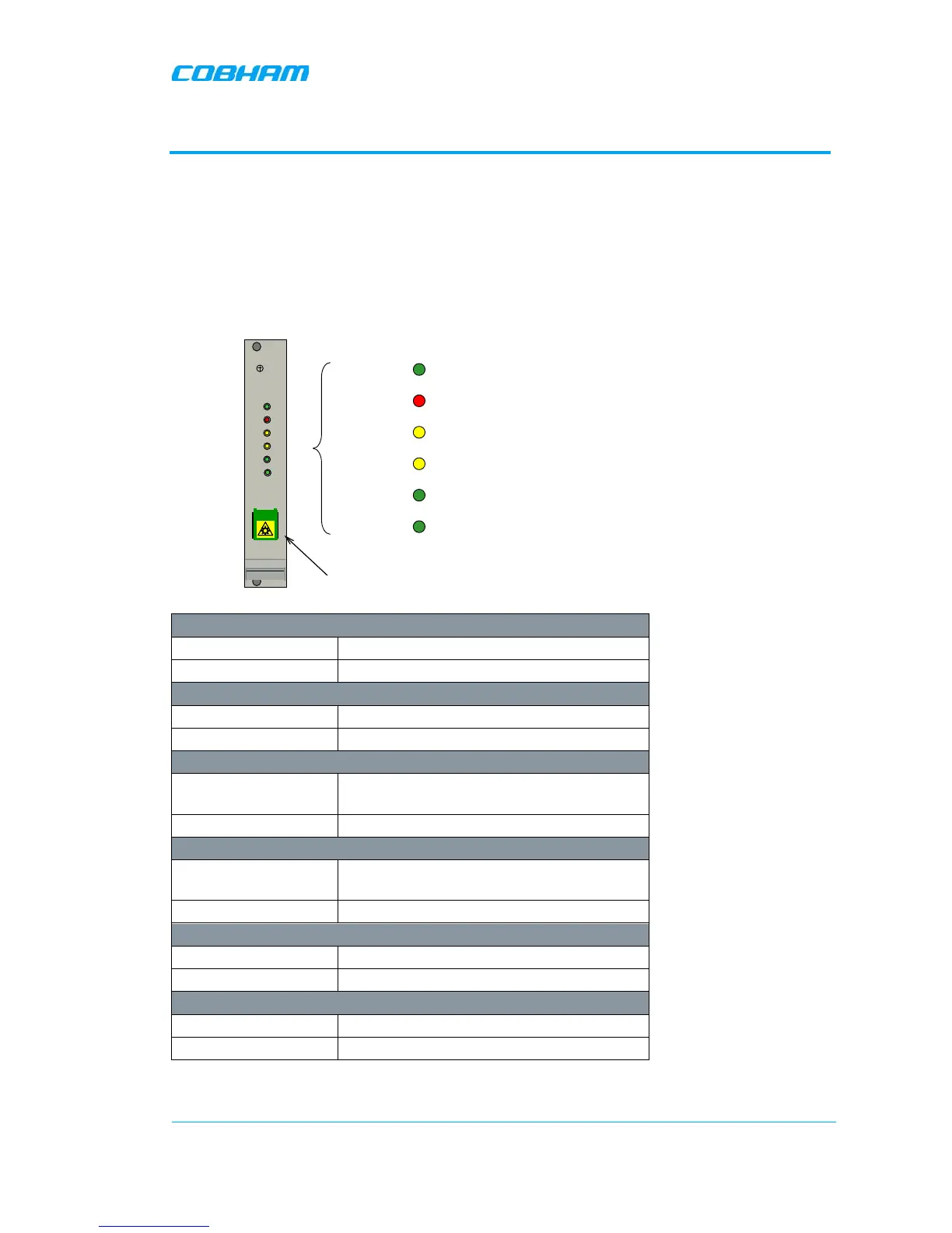
4.1.1 WDM Module LEDs
On the Fiber Optic Converter module there are six LED indicators; one for power status, one for
error, two for the data communication and two for the RF signals.
LED 1, Power, Green
On Unit is powered on
Off Unit has no power
LED 2, Error, Red
On Error detected
Off No error
LED 3, UL Data, Yellow
On
Communication via the opto module is
ongoing in the uplink direction
Off No communication
LED 4, DL Data, Yellow
On
Communication via the opto module is
ongoing in the downlink direction
Off No communication
LED 5, Opto Rx, Green
On Input opto level OK
Off Input opto level below threshold
LED 6, Opto Tx, Green
On Output opto level OK
Off Output opto level below threshold
ERR
PWR
UL
DATA
DL
DATA
OPTO
Rx
OPTO
Tx
SC/APC
PWR Indicates that the power is on
ERR Indicates that there is something wrong in the module
UL DATA Ongoing communication in the uplink direction
DL DATA Ongoing communication in the downlink direction
OPTO Rx Received signal on fiber channel
OPTO Tx Transmitted signal on fiber channel
Fiber link connection
 Loading...