OPTICAL MASTER UNIT MARK I
PRODUCT DESCRIPTION AND USER’S MANUAL
Cobham Wireless – Coverage Date: 4-Jan-18 www.cobham.com/wireless
Document number:A1829300UM Rev. 3.1
Page | 15
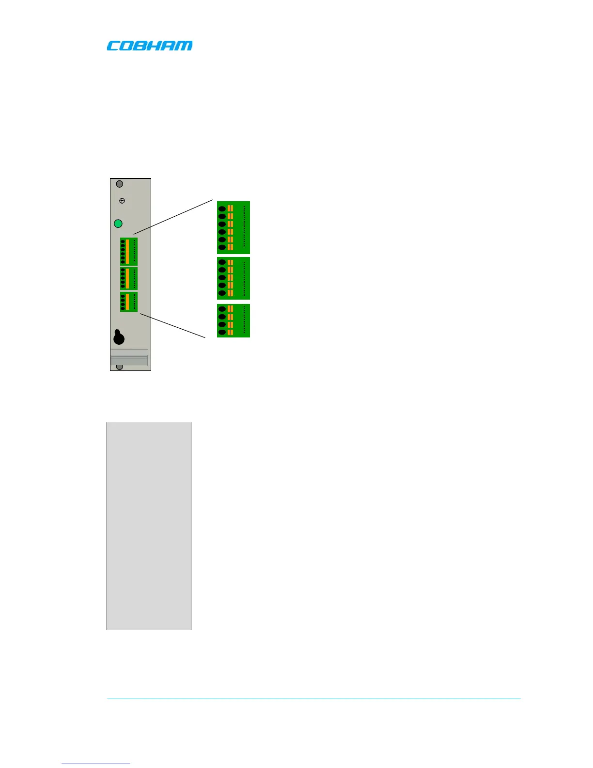
2.4.5 External Alarm and Relay Connections
Four external alarm sources can be connected to the External Alarm and Battery Module via the
patch panels. These sources must generate a voltage between 12 and 24VDC. The presence or
absence of this voltage will trigger the alarm depending on how the alarm thresholds have been
configured. The module can also supply +15V to external alarm sources. The maximum allowed load
on this supply is 100mA.
The relay can be configured to trigger on any number of internal and external alarms. The maximum
current through the relay is 100mA.
External Alarm and Battery Module with pin out for external alarms and relay
The panels can be used for wires of up to 0.5mm
2
. To connect a wire, press the yellow lever with a pen or other
pointy item, insert the wire and release the lever.
Connect external
alarms
Four external alarm sources can be connected to the External Alarm and
Battery Module via the patch panels. These sources must generate a
voltage between 12 and 24 VDC. The presence or absence of this voltage
will trigger the alarm depending on how the alarm thresholds have been
configured. The module can also supply +15V to the external alarm
sources. The maximum allowed load on this supply is 100mA.
The External Alarm and Battery Module contains a relay that can be
connected to an external device to indicate an alarm. The relay can be
configured to trigger on any number of internal and external alarms. The
maximum current that can be run through the relay is 100mA.
The external alarm wires are linked to the module via patch panels. These
panels can be released from the module for easier access at installation.
The panels can be used for wires of up to 0.5 mm
2
. To connect a wire,
press the yellow lever with a pen or other pointy item, insert the wire and
release the lever.
PWR
Battery
Power
GND
GND
External alarm 1A
External alarm 1B
External alarm 2A
External alarm 2B
Relay Output 1A
Relay Output 1B
+15VDC Output
GND
GND
External alarm 3A
External alarm 3B
External alarm 4A
External alarm 4B
1
2
3
4
5
6
7
8
9
10
11
12
13
14
15
1
2
3
4
5
6
7
8
9
10
11
12
13
14
15
On
Off
 Loading...