OPTICAL MASTER UNIT MARK I
PRODUCT DESCRIPTION AND USER’S MANUAL
Cobham Wireless – Coverage Date: 4-Jan-18 www.cobham.com/wireless
Document number:A1829300UM Rev. 3.1
Page | 16
2.4.6 Modem Connections
Connect the
modem
If the OMU is equipped with a wireless modem an antenna for the modem
is necessary. This can be realized either via a separate antenna or via a
coupler on the RF in/out port in the OMU.
The coupler can only be used if the OMU runs on the same frequencies as
the modem and the Rx/Tx is combined (there is a duplex filter).
The separate antenna is plugged in to the Antenna connector on the far
right end of the OMU. The connector is SMA.
If the OMU is equipped with a PSTN modem the connector is placed in the
Modem Unit. The connector is RJ11
The Ethernet connection is placed on the Control Module. The connector is
RJ45.
Either a separate antenna is connected to the modem antenna port, or the connection is be made via
a coupler connected to the RF input to the OMU. The latter alternative can only be used if the OMU
runs on the same frequency as the wireless modem and is equipped with a duplex filter.
2.4.6.1 OMUs without Duplex Filter
OMUs that are not equipped with a duplex filter and use a
wireless modem has a modem antenna port to the
rightmost side of the rack.
An external antenna can be connected to the “Modem
Ant” port.
The connector is SMA type.
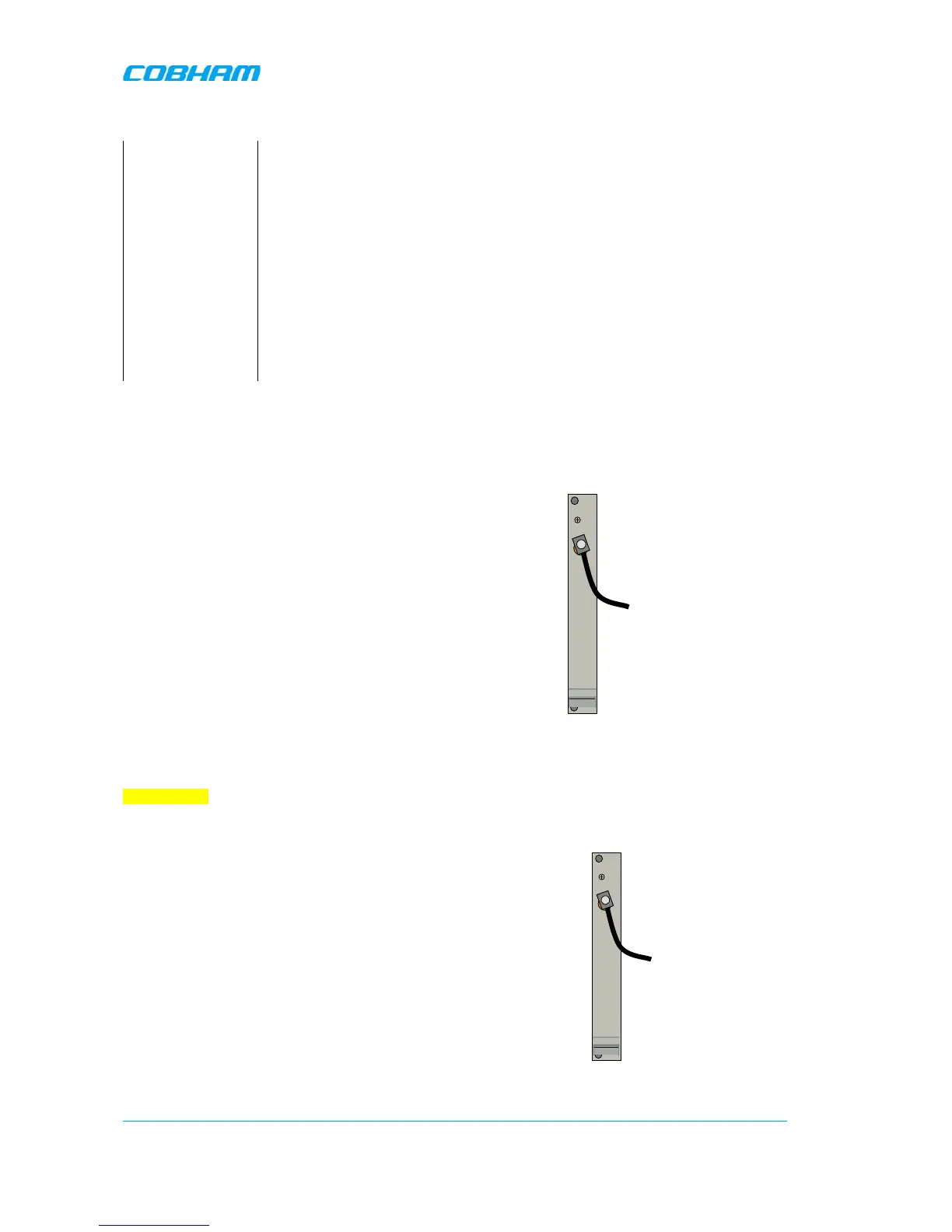
2.4.6.2 OMU with Duplex Filter
OMUs that are equipped with duplex filters and a wireless modem are of two kinds:
Alternative 1
Alternative 2
The OMU and the wireless modem operate on different
bands (for example an OMU for TETRA with a GSM
modem)
In this case the OMU will have one port where an external
antenna can be connected.
The connector is SMA type.