OPTICAL MASTER UNIT MARK I
PRODUCT DESCRIPTION AND USER’S MANUAL
Cobham Wireless – Coverage Date: 4-Jan-18 www.cobham.com/wireless
Document number:A1829300UM Rev. 3.1
Page | 10
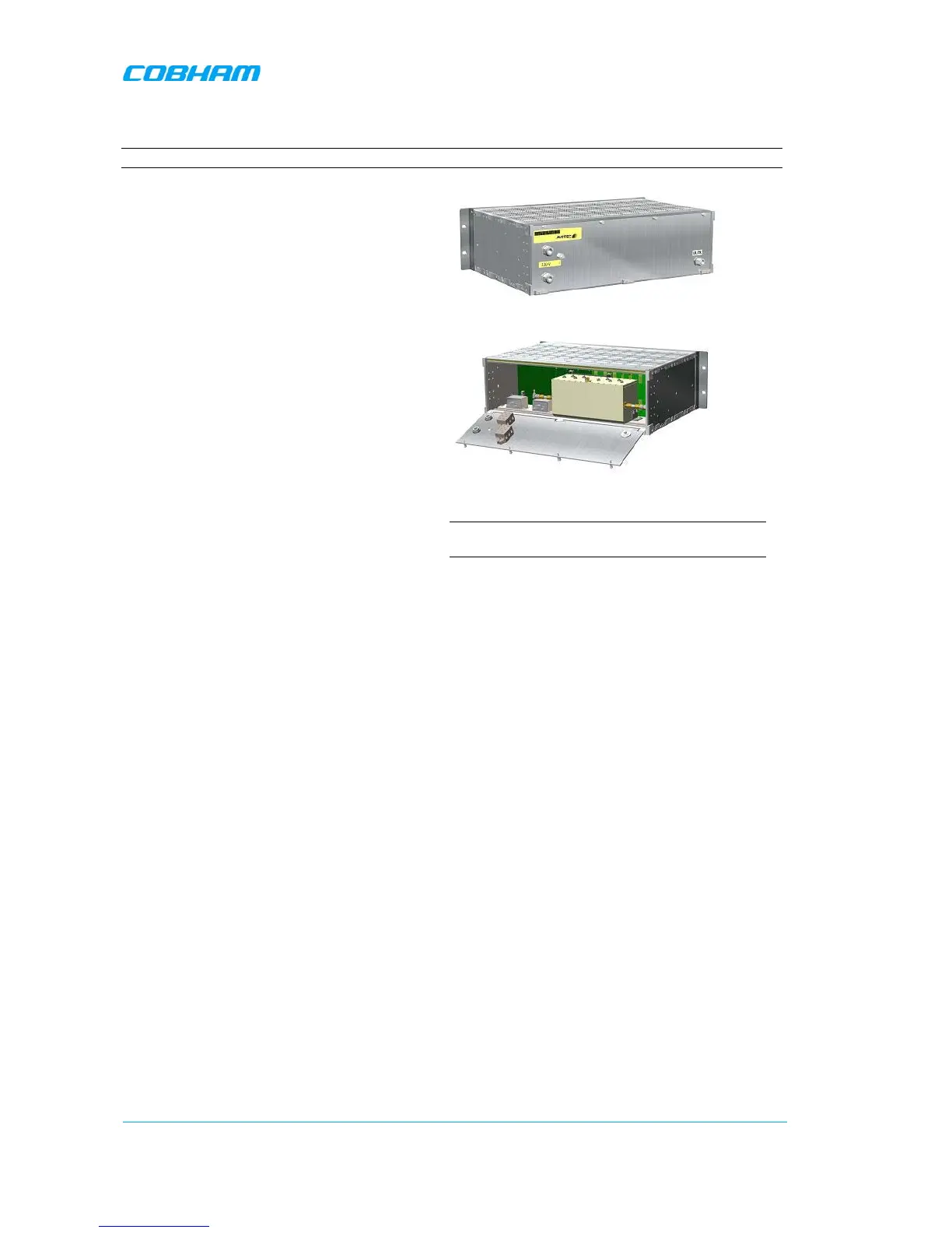
1.5 Rear Panel
Note: The rear-panel layout can vary depending on the configuration.
The rear panel provides the following
functions:
• Power - Plinths for power connections –
requires opening the rear panel.
• GND - screw for earthing
• RF input - N-connector for RF input. There
is one connector if the Rx/Tx input is
combined and two connections if the Rx
and Tx are to be fed separately.
To gain access to the plinths for power
connections, duplex filter (for some models),
optional attenuators and optional coupler the
back panel needs to be opened. It is fastened
with 4 screws.
1-14. OMU with one RF In/Out
The images to the right show the closed panel
(top) and open panel (bottom)
input power connections.
Figure
1-15.Inside of Back Lid
NOTE: Includes two plinths for power connections, a
duplex filter and one RF in/out