OPTICAL MASTER UNIT MARK I
PRODUCT DESCRIPTION AND USER’S MANUAL
Cobham Wireless – Coverage Date: 4-Jan-18 www.cobham.com/wireless
Document number:A1829300UM Rev. 3.1
Page | 12
2.4 Connections
2.4.1 Single Sector RF Connections
NOTE: For multi-sector configuration using 6-way RF Interface cards, refer to section 3.12.3.
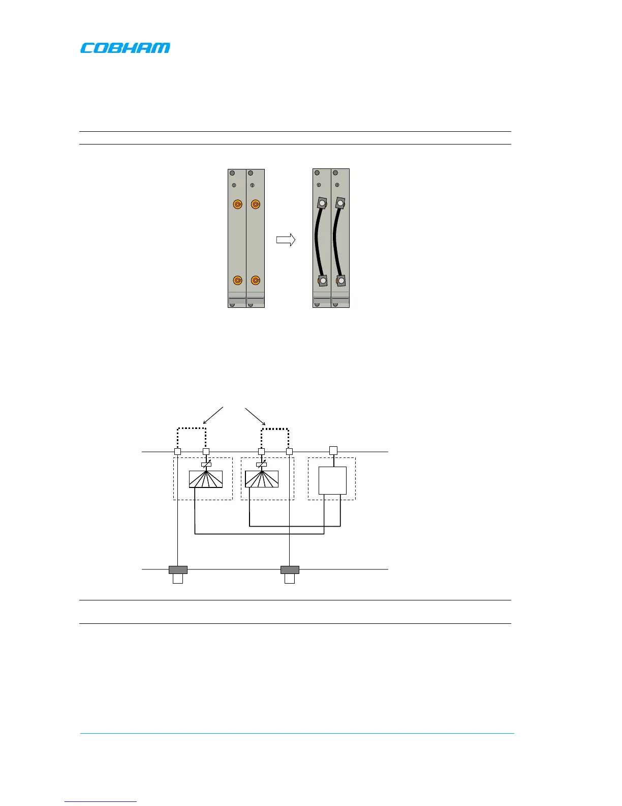
The modules can to be configured in two ways as shown in the illustration below.
Figure
2-2. Single Sector Configuration
• In Alternative 1 the connectors on each module are linked and the input to the OMU is made via
the N-connectors on the back of the OMU. See also illustration below.
• In Alternative 2 the input to the OMU is made via the QMA connectors marked RF in/RF out.
NOTE: In the illustration above only one Fibre Optic Converter is shown. The other converters are connected in
a corresponding way.