OPTICAL MASTER UNIT MARK I
PRODUCT DESCRIPTION AND USER’S MANUAL
Cobham Wireless – Coverage Date: 4-Jan-18 www.cobham.com/wireless
Document number:A1829300UM Rev. 3.1
Page | 6
Label Unit Description Allocated Slots
and B)
8. Modem Antenna
connections
This module is optional. This is used
for OMUs with wireless modems
installed that need a separate
antenna. This module can also be
equipped with two connectors.
14
1.4.1 WDM Fibre Optic Converter
Caution!
Un-terminated optical receptacles may emit laser radiation.
Do not stare into beam or view with optical instruments.
These modules perform the following functions:
• Provides RF to optical signal conversion in both
directions.
• Downlink and uplink optical signals are combined
using WDM – only one fibre is required.
• Each WDM Fibre Optic Converter in the OMU works in
parallel with a corresponding unit in the repeater
which is linked via the fibre (SC/APC port).
• A pilot tone can be sent between the Fiber Optic
Converters in the OMU and the repeater to define the
loss in the fibre. Based on this information the
repeater automatically adjusts the attenuation to
compensate for the fibre loss.
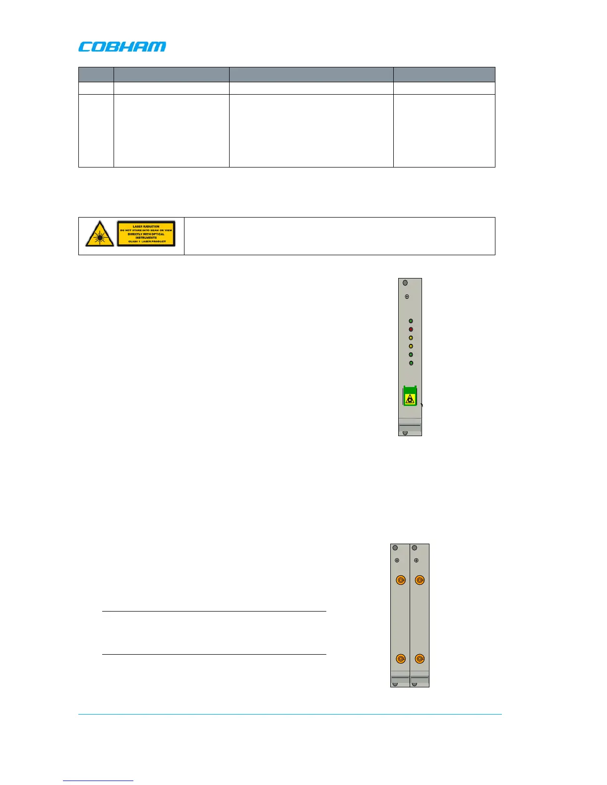
• On the Fibre Optic Converter module there are six
LED indicators; one for power status, one for error,
two for the data communication and two for the RF
signals.
Figure
1-6.WDM Fibre Optic
Converter
1.4.2 UL Combiner and DL Splitter
These modules perform the following functions:
• Combine and distribute the RF signals between the
OMU’s RF port and the Fiber Optic
• Contain attenuators used to set the master signal
levels in the downlink and uplink.
Note: By default, the module ports are interconnected *UL
In to RF out) to allow RF connections at the rear of the
unit. However, these may be reconnected to allow RF
connections at the front of the unit.
Figure
1-7. UL Combiner/DL Splitter
ERR
PWR
UL
DATA
DL
DATA
OPTO
Rx
OPTO
Tx
SC/APC