OPTICAL MASTER UNIT MARK I
PRODUCT DESCRIPTION AND USER’S MANUAL
Cobham Wireless – Coverage Date: 4-Jan-18 www.cobham.com/wireless
Document number:A1829300UM Rev. 3.1
Page | 3
1.3 OMU Installation Configurations
The OMU can be installed in several configurations:
• Basic configuration of a single OMU installed at the BTS
• Expanding the system by either:
• Linking several OMUs (up to four)
• Using laser systems with three or four colours.
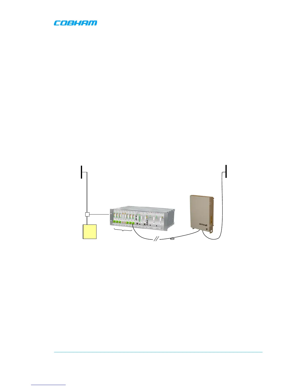
1.3.1 Single OMU Topology
The following figure illustrates the connections for a single OMU installed at the BTS. The OMU
supports up to six Repeaters, where each repeater is connected via optic fibre to an RF/Optic
converter module on the OMU. Each OMU supports up to six RF/Optic converters – for connections to
up to six Repeaters.
In the downlink the radio signal is tapped from a BTS using a coupler installed in series with the
BTS’s antenna cable. The Fibre Optic Converter in the OMU converts the RF signal to an optical signal
and sends it to the repeater over a fibre.
In the uplink the Fibre Optic Converter receives the optical RF signal from the repeater, converts it to
electrical RF signal and sends it to the BTS. The signal is transferred to the antenna cable using a
coupler.
Figure 1-2. Example of Single OMU Topology