OPTICAL MASTER UNIT MARK I
PRODUCT DESCRIPTION AND USER’S MANUAL
Cobham Wireless – Coverage Date: 4-Jan-18 www.cobham.com/wireless
Document number:A1829300UM Rev. 3.1
Page | 17
2.5 Connecting Power and Power-up
CAUTION!
Make sure the antenna cables or 50 ohm terminations are connected to the OMU’s antenna
connectors before the OMU is switched on.
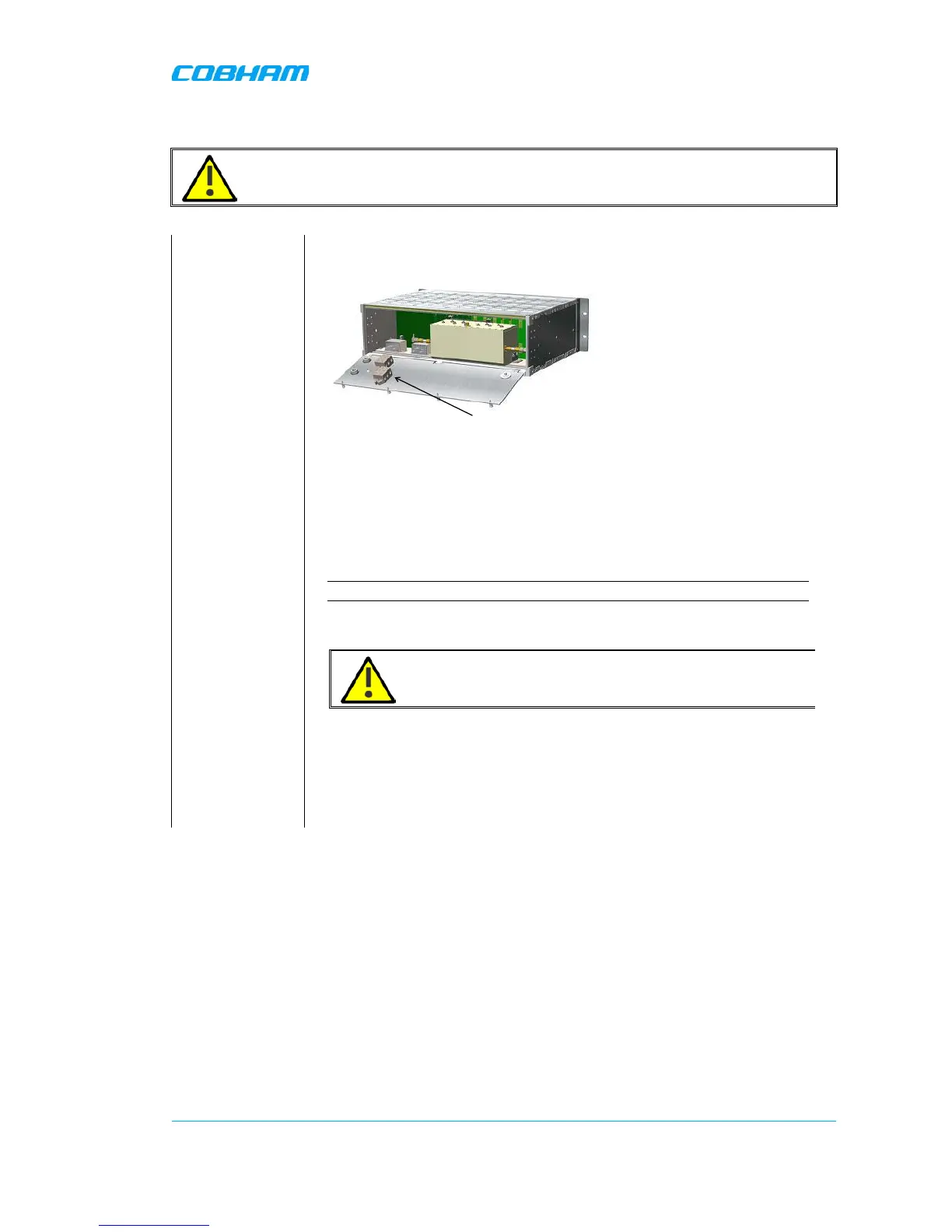
Supply Power to
the OMU
The power feed to the OMU is attached via plinths found on the inside of
the back cover.
There are two plinths on the inside of the back panel. If two modules
with the same power feed are installed these plinths should be
interconnected.
Each OMU unit can be equipped with one or two power supplies. Either
two of the same type or two of different voltage.
There are power supplies for 115 - 230VAC 50/60 Hz and 24 – 48 VDC. .
NOTE: Be careful to get the polarity right.
Each Power Supply can be switched off using the switches on the front
panel.
CAUTION!
Even if the power supplies are switched off the OMU still has live
power from the power input on the back.
Check Control
Module LEDs