Section 15–Changing the Boresight (Pan)-Single SmartBeam™ ATC200-LITE-USB Teletilt
®
RET System
15-2 October 2014 Bulletin 639536 • Revision L
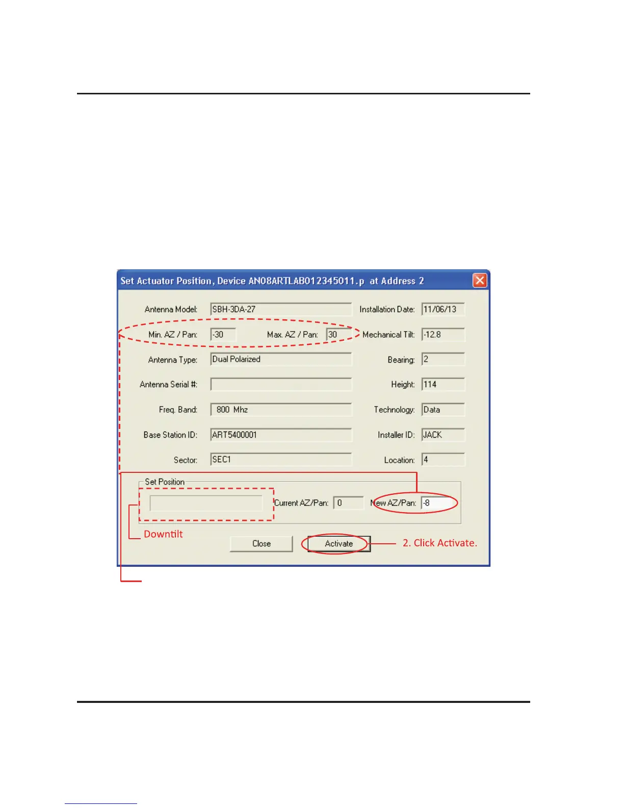
4. The Set Actuator Position screen will appear (Figure 15-2).
Note, all parameters that can be configured are displayed on this screen. This information may
be used as a reference to help determine the new boresight (pan) setting. However, configuration
items cannot be changed from this screen. All changes to configuration items must be done with
the Configuration screen as discussed in Section 10.
5. Enter the new azimuth in the New AZ/Pan text entry field to change the boresight (pan). Note that
the allowed AZ/Pan range is displayed in the Min AZ/Pan and Max AZ/Pan fields in the top part
of the screen. Any degree of azimuth within this range may be entered. Values may be entered
as whole degrees (Figure 15-2).
Examples: Five degrees boresight (pan) may be entered as 5 or 5.0.
Figure 15-2. Configuring New Boresight (Pan) Setting.
1. Enter a new boresight (pan) azimuth.
Refer to the Min. AZ/Pan and Max. AZ/Pan values to ensure that the
new pan azimuth entered is within the range for the antenna
model. Values may be entered as whole degrees.
Progress
Display.