EasyManua.ls Logo

Condair EL2 - Electric Installation; Wiring Diagram Condair EL2

Condair EL2
72 pages
Print Icon
To Next Page IconTo Next Page
To Previous Page IconTo Previous Page
Loading...
39
5.6 Electric installation
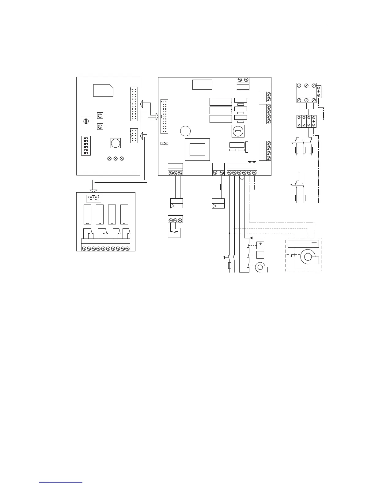
5.6.1 Wiring diagram Condair EL2
A1 Continuous controller (active 0-10V)
A2 On/Off controller (passive 24VDC), set jumper on JP1
A3 On/Off control (active 230VAC)
B1 Ventilation interlock
B2 Airowmonitor
B3 Safety humidistat
F1 Internal fuse powerboard(6.3A,slowacting)
F2 Externalfuseheatingvoltagesupply
F3 Externalfusecontrolvoltagesupply
F4 External fuse 230V On/Off control
H1 Remoteoperatingandfaultindication(option“RFI”)
J Shortcircuited,ifnoexternalmonitoringdevicesareconnected
JP1 Jumper On/Off mode
K External safety chain (230V/5A)
K1 Maincontactor(forconnectingtheheatingvoltagesupplytotheunit)
M Fan unit FAN3 EL2
Q2 Externalserviceswitchheatingvoltagesupply
Q3 Externalserviceswitchcontrolvoltagesupply
S1 Rotaryswitch"Cylindertype”
S2 Potentiometer“Drainfactor”
S3 Potentiometer“Powerlimitation”
S4 DIPswitch“Generalunitsettings”
X0 Connectionterminalheatingvoltage(optionTHV)
X1 Connectionterminalcontrolsignal
X2 Connection terminal On/Off control active
X3 Connectionterminalcontrolvoltage
Controlboard
Powerboard
L1
Q2
K1
X0
F2
L1 L2 L3
L1 L2 L3
L1 L2 L3
Heating
400 V/3~/50..60 Hz
230 V/3~/50..60 Hz
Q2
F2
L1 N PE
230 V/1~/50..60 Hz
EL2 Card
red yellow green
F1
(6.3 AT)
CONT.SIGN
V+ IN GND
X2 X3
VD
MAIN SUPPLY
L1 N SC1SC2
LEV.SENSOR
Driver board
CPU board
J1
X1
CURRENT SENSOR
CPU BOARD
1 2
On/Off
JP1 must be plugged
B3
K
B2
B1
J
Q3
230V/1 50...60Hz
L1 N
F3
On/Off Mode
JP1
+
0-10V
A1
H1
A2
A3
F4
230V
L1’
1 2 3 4 5 6 7 8 9 10
Error Service Steam Unit On
Cylinder
Drain Factor
Power Limit
Manual Drain
Low Conduct.
Standby Drain
Force Drain
Cylinder A/D
GFCI-Mode
Offset
Settings
0
DriverRFI
ON
1 2 3 4 5 6
J8
J1
V+ IN GND
X5
X7
X8
X4
1 2 3 4
SWITCH
1 2 3 4
INLET
1 2
CONTACTORDRAIN
∆p
max.
PE
M
L1 N
PE
S1
S2
S3
S4

Table of Contents

Related product manuals