5.6.2 Notes on electric installation
Important notes
– The electric installation must be carried out according to the wiring diagram in chapter 5.6.1, the
notesonelectricinstallationaswellastheapplicablelocalregulations.Allinformationgivenin
thewiringdiagrammustbefollowedandobserved.
– All cables must be lead into the unit via the cable openings equipped with cable glands (e.g. op-
tion“CG-cablegland”).Thecablefortheheatingvoltagesupplymustbeleadintotheunitfrom
the bottom via the cable opening equipped with the clamp strap. Fix the cable with the clamp
strap.
– Make sure the cables do not scrub on any components.
– Maximum cable length and required cross section per wire must be observed.
– Thesupplyvoltagesmustmatchtherespectivevoltages(heatingandcontrolvoltage)statedin
the wiring diagram.
Heating voltage supply Up
CAUTION!
Beforeconnecting,ensurethatthemainsvoltagecorrespondswiththeheating voltage for the
unit(seetypeplate).
The Condair EL2 is to be connected to the mains supply in accordance with the wiring diagram, via
a service switch “Q2”(disconnectingdevicewithaminimumcontactopeningof3mmisanes-
sentialrequirement)andan fuse group “F2”(essentialrequirement,fusesaretobeasdetailedin
thefollowingtable).Thesupplywiringistobefedintotheunitviaatension-relievingdevice(cable
gland)andconnectedtotheterminalsofthemaincontactor“K1”.
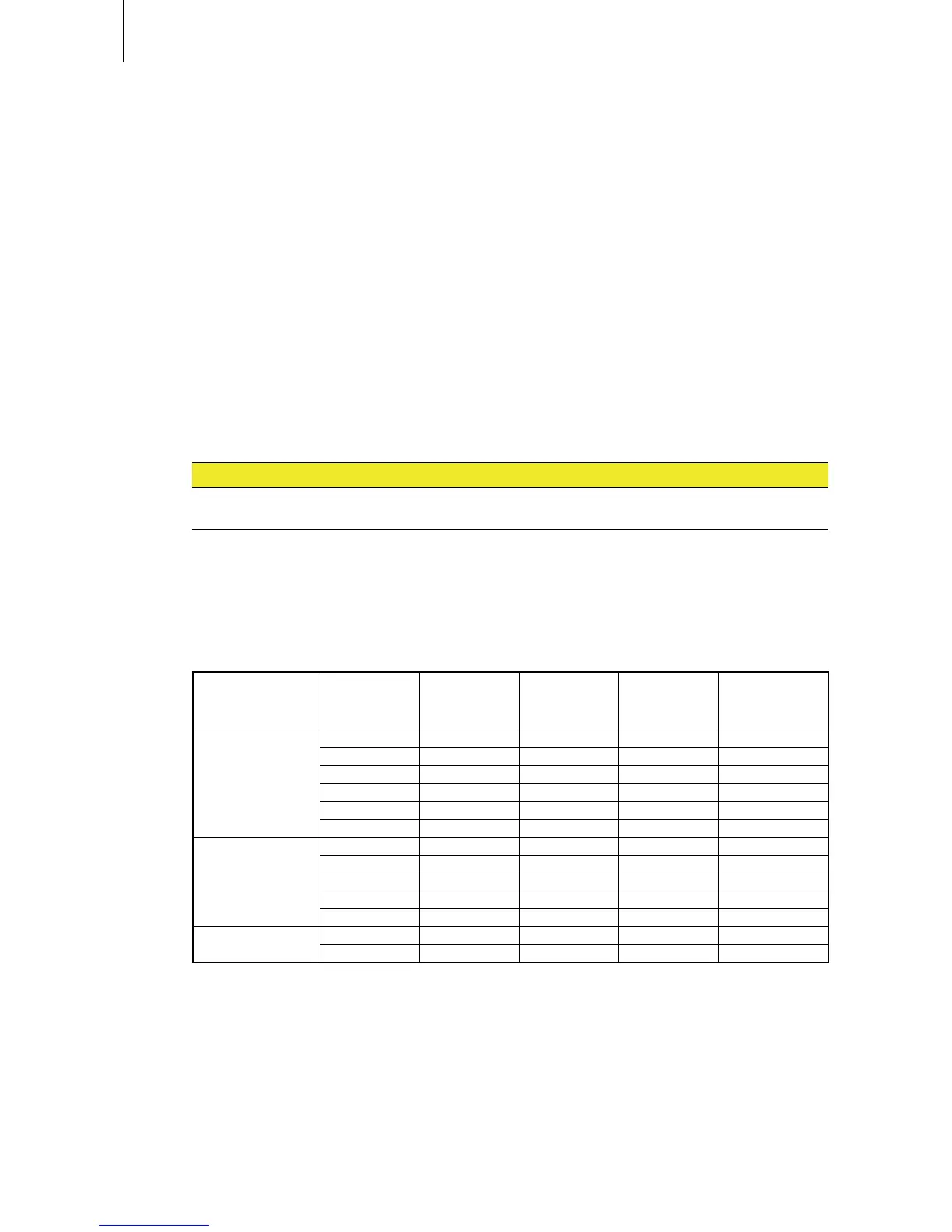
Heating voltage Max. steam
capacity
[kg/h]
Condair EL2 .. Nominal power
[kW]
Nominal
current
[A]
Main fuses F2
[A]
400V3
(400V/3~/50...60Hz)
5 5 3.8 5.4 3x 10
8 8 6.0 8.7 3x 10
15 15 11.2 16.2 3x 20
23 23 17.3 24.9 3x 35
32 32 24.0 34.6 3x 50
45 45 33.7 48.7 3x 63
230V3
(230V/3~/50...60Hz)
5 5 3.8 9.4 3x 20
8 8 6.0 15.1 3x 20
15 15 11.2 28.2 3x 40
23 23 17.3 43.3 3x 63
32 32 22.5 56.5 3x 63
230V1
(230V/1~/50...60Hz)
5 5 3.8 16.3 20
8 8 6.0 26.1 35
Thecross-sectionofthemainscablemustcomplywiththeapplicablelocalregulations.