Control signal
– External continuous humidity controller 0-10V (A1)
Anexternalhumiditycontinuouscontrolleristobeconnectedtothecontacts“IN”(+)and“GND”
(–)oftheterminalblock“X1”.
– 24 VDC On/Off humidistat (passive)
An24VDCOn/Offhumidistatistobeconnectedtothecontacts“V+”and“IN”oftheterminal
block “X1”.
Note:forthe24VDCOn/Offcontrolajumpermustbeseton“JP1”.
– 230V On/Off control (active)
Thesignallineofa230VOn/Offcontrolistobeconnectedtothecontact“VD”oftheterminal
block“X2”viaexternalfuse“F4”(max.10A,slow-acting).
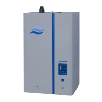
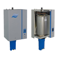
Connecting the fan unit FAN3 EL2
Refertotheseparatedocumentationofthefanunit.
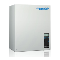
5.6.3 Unitconguration
Allsettingcomponentsfortheunitcongrationarelocatedonthecontrolboard:
– Rotaryswitch“Cylinder”: cylindertype
– Potentiometer“DrainFactor”: drainfactor
– Potentiometer“PowerLimit”: powerlimitation
– DIPswitch“Settings”: generalsettings
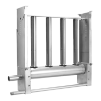
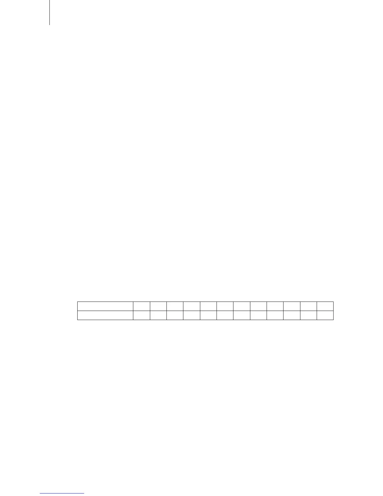
Settingthesteamcylindertype(“Cylinder”)
Usetherotaryswitch“Cylinder”toselectthetypeofsteamcylinderused.
Position 0 1 2 3 4 5 6 7 8 9 A B
Cylinder type 342 343 344 363 444 464 544 564 654 674 644 664
Setting the drain factor
Usethepotentiometer“DrainFactor”tosetthedrainfactor(settingrange:0.5...2.0,factorysetting:
1.0).
Setting the power limitation
Usethepotentiometer“PowerLimit”tosetthepowerlimitationin%ofthemaximumcapacity(setting
range:30...100%,factorysetting:100%).