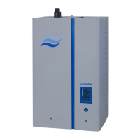
Control voltage supply Uc
CAUTION!
– Beforeconnecting,ensurethatthemainsvoltagecorrespondswiththecontrol voltage of the
unit (230 V/1 50…60 Hz).
– Thehumidiermustonlybeconnectedtoamains supply with a protective conductor.
The connection to the control voltage Uc is made in accordance with the wiring diagram, to the ter-
minal“X3” on the power board. The customer is to install a service switch Q3 in the supply line
(allpoledisconnectingdevicewithaminimumcontactopeningof3mm)andanF3 fuse (max. 10
A slow acting) (thesearebothessentialrequirements).
Thecross-sectionofthemainscablemustcomplywiththeapplicablelocalregulations(minimum
of1.5mm
2
).
External safety circuit
Toguaranteethesafetyofthehumidicationsystem,monitoringtheoperationbymeansofasafety
circuit is an absolute requirement.
To accomplish this, the potential-free contacts (max. contact loading 250V/5A)ofexternalmoni-
toringdevices(e.g.safetyhighlimithumidistat,airowmonitor,ventilationinterlock,etc.)arecon-
nectedinseriestothecontacts“SC1”and“SC2”oftheterminalblock“X3” in accordance
with the wiring diagram.
DANGER! Danger of electric hazard!
Themainsvoltageisconnectedtoterminalblock“X3”(upto240V).Thesteamhumidiermust
thereforebeisolatedfromthemainssupply(heatingandcontrolvoltage),beforestartingthecon-
nection work.
If,forwhateverreason,noexternalmonitoringdevicesareconnected,aconnectingbridge“J”must
beinstalledonthecontacts“SC1”and“SC2”oftheterminalblock“X3”.
Donotapplyanyextraneous voltage to the terminals.
Thecross-sectionofthecablemustcomplywiththeapplicablelocalregulations(minimumof1mm
2
).
RemoteoperatingandfaultindicationH1(Option“RFI”)
TheoptionalremoteoperatingandfaultindicationPCBistobeconnectedtothecontrol
boardvia
theterminal“J1”.TheoptionalremoteoperatingandfaultindicationPCBcontainsfourpotential-free
relaycontactsfortheconnectionofthefollowingoperatingandfaultindications:
– “Error”: Thisrelayisactivatedifanerrorispresent.
– “Service”: Thisrelayisactivatedwhenthesetserviceintervalhasexpired.
– “Steam”: Thisrelayclosesassoonastheunitproducessteam.
– “UnitOn”: Thisrelayclosesassoonastheunitisswitchedonviathemainswitch.
The maximum contact loading is 250V/5A.
Appropriatesuppressormodulesaretobeusedfortheswitchingofrelaysandminiaturecontac-
tors.
Note:Theminimumcrosssectionofthesupplycablemustcomplywiththelocalregulations.