104 Condair CHR and CHR-NA
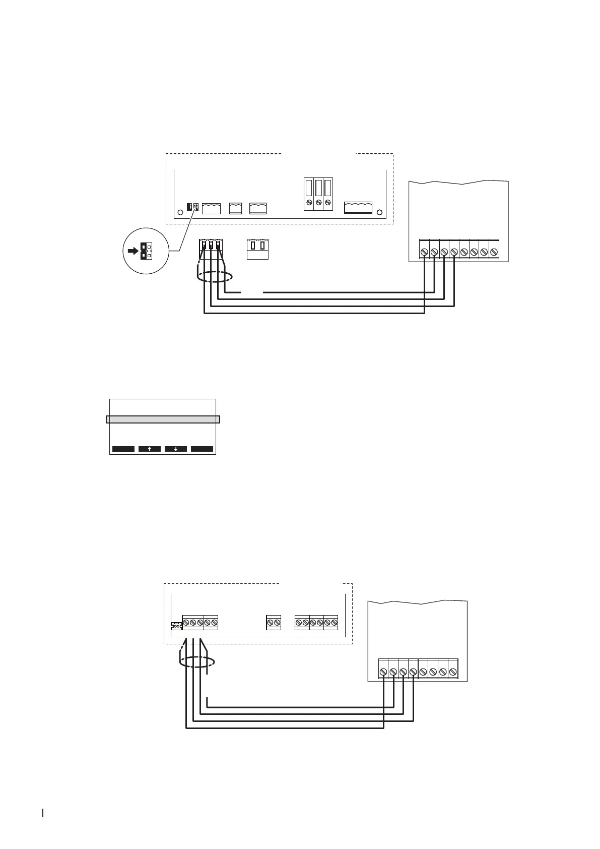
7.8.3 Connecting the CHR or CHR-NA to the Condair CP3mini
1. Connect the CHR or CHR-NA to the corresponding terminals of terminal block "X1" on the power
board of the Condair CP3mini according to the following diagram.
Note: The voltage supply of the CHR or CHR-NA is established via the terminals "V+" and "GND"
of terminal block "X1" or via an external 24 V AC/DC voltage supply.
CHR / CHR-NA
24V AC/DC
DO1
DO1
DO2
DO2
RT
RT
0V/GND
1 2 3 4 5 6 7 8
CONT.SIGN
V+
GND CTRL
X1 X4 X6
CTRL V+
1 21 21 2 3
GND
BASIC
0-10V
On/Off
24V
5V
PRO
JP4
JP3
JP2
JP1
LIMGND SC1SC2
SAFETY
SC1SC2
24V
5V
JP2
JP1
Condair CP3 mini
PWR
MAIN SUPPLY
X9
L
N PE
X8
N L SW N SWL
24 VDC
Power board
Condair CP3mini
2. On the power board of the Condair CP3mini: set a Jumper on JP2-24 V and remove the Jumper on
JP1-5V (if a jumper is set).
3. Set the Condair CP3mini into operation, go to the setup level of the software and set the parameter
"Hum.Control" to "24OnOff" (refer to the Condair CP3mini installation and operating instructions).
Controls
Hum.Control :24VOnO
Hum.Setpoint:Set
Lim. Control:O
SignalSource:Analog
Esc Set
7.8.4 Connecting the CHR or CHR-NA to the Condair ABS3
Connect the CHR or CHR-NA to the corresponding terminals on the control board of the Condair CP3mini
according to the following diagram.
Note: The voltage supply of the CHR or CHR-NA is established via the terminals "24V" and "GND" of
the terminal block or via an external 24 V AC/DC voltage supply.
K1N L1 K2 K3
24V LEVELGND IN
NTC
Condair ABS3
CHR / CHR-NA
24V AC/DC
DO1
DO1
DO2
DO2
RT
RT
0V/GND
1 2 3 4 5 6 7 8
24 VDC
Control board
Condair ABS3