61Condair DCC and DCC-NA
4.8 Connecting the DCC and DCC-NA to Condair units
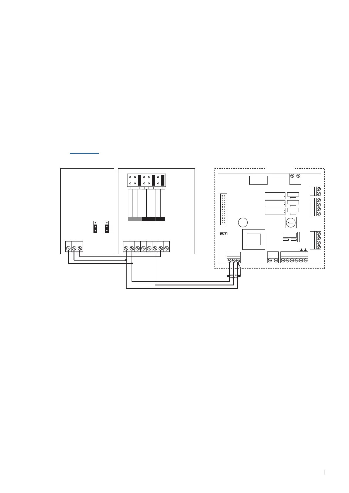
4.8.1 Connecting the DCC to the Condair EC
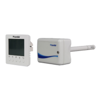
1. Connect the Condair CDC sensor to the Condair DCC controller according to the wiring diagram
below. Then, set the control signal to "0-10V" using the jumpers "JP1" and "JP3" on the control
board of the sensor.
2. Connect the Condair DCC controller to the corresponding terminals on the driver board of the Condair
EC according to the wiring diagram below.
Note: The voltage supply of the DCC is established via the terminals "V+" and "GND" of terminal
block "X1" or via an external 24 V AC/DC voltage supply.
3. Set the input and the output signal of the controller to "0-10V" using the Jumper "AO" and "AI" on
the control board of the Condair DCC.
4. Set the Condair DCC to the desired humidity setpoint (see following programming instructions in
Section 4.9).
Condair EC
UI2
UI1
AO1
24 V
0V/GND
**
24V AC/DC
0V/GND
H OUT
2
3
1
2
3
1
***
1 2 3 1 2 3 4 5 6 7 8
JP1 JP3
F1
(6.3 AT)
CONT.SIGN
V+ IN GND
X2 X3
VD
MAIN SUPPLY
L1 N SC1SC2
LEV.SENSOR
J1
X1
CURRENT SENSOR
CPU BOARD
1 2
On/Off Mode
JP1
X5
X7
X8
X4
1 2 3 4
SWITCH
1 2 3 4
INLET
1 2
CONTACTORDRAIN
0...10V
0...20mA
RT or Dry-Contact
UI2
0...10V
0...20mA
0...10V
0...20mA
RT or Dry-Contact
AO
UI1
Driver board
Condair EC
DCC
Controller
CDC
Sensor