24 Condair CDC, CDC-NA, CDC-ST and CDC-SL
2.8 Connecting the CDC, CDC-NA, CDC-ST or CDC-SL to Condair units
2.8.1 Connecting the CDC or CDC-NA to the Condair DL
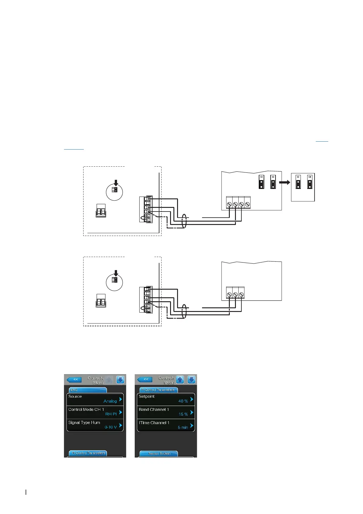
1. Connect the CDC or CDC-NA (signal Y) according to the appropriate wiring diagram (see below) to
the corresponding terminals of the terminal block "X16" on the driver board of the Condair DL.
Note: The voltage supply of the CDC or CDC-NA is established via the terminals "24/10V" and "GND"
of terminal block "X16" or via an external 24V AC/DC voltage supply.
2. On the driver board of the Condair DL: set a Jumper on JP4-24V and remove the Jumper on JP5-
10V (if a jumper is set).
3. Only for CDC: Set the output signal of the CDC to "0-10V" using the Jumpers JP1 and JP3 on the
control board of the CDC.
Note: other output signal settings (e.g. 4-20mA) are also possible, see CDC jumper settings in Sec-
tion 2.7.
4. Set the Condair DL into operation, go to the control menu of the unit software and set the parameters
"Source" to "Analog", "Control Mode CH 1" to "RH PI", "Signal Type Hum" to "0-10V" (or to output
signal set on CDC) or "2-10V" (for CDC-NA) and the parameters "Setpoint", "Band Channel 1" and
"ITime Channel 1" to the desired values (refer to the Condair DL operation manual).
0...10V
JP1
2
3
1
JP3
2
3
1
X1
X16
JP5: 10V
JP4: 24V
SC2
SC1
24/10 V
TMP
GND
HUM
24V E
Enable
24 VDC
24V AC/DC
0V/GND
AO RH
AO T
JP1
2
3
1
JP3
2
3
1
***
1 2 3 4
X1
X16
JP5: 10V
JP4: 24V
SC2
SC1
24/10 V
TMP
GND
HUM
24V E
Enable
24 VDC
24V AC/DC
0V/GND
H OUT
1 2 3
Condair DL
Condair DL
Driver board Condair DL
CDC-NA (Signal Y)
CDC (Signal Y)
Driver board Condair DL