142 Condair APS and APS-NA
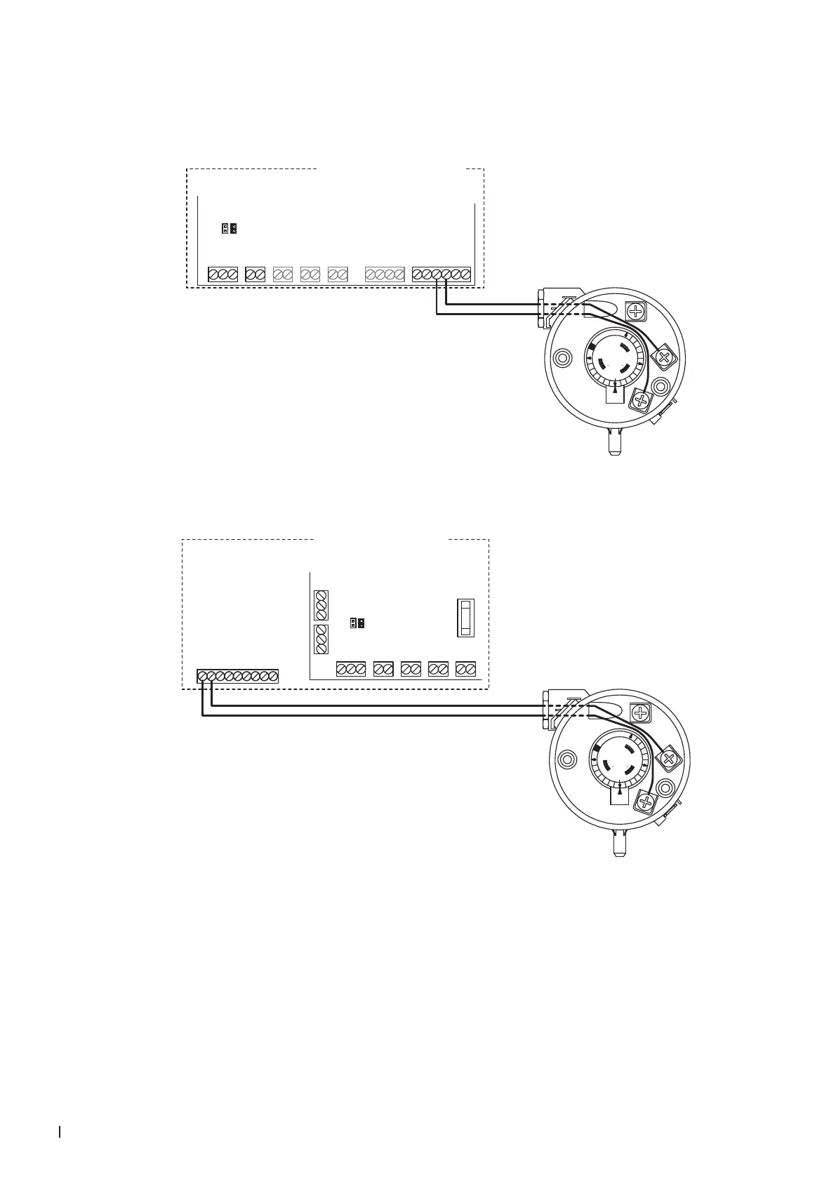
11.7.3 Connecting the APS or APS-NA to the Condair RS
Connect the APS to the corresponding terminals on the driver board of the Condair RS/RS OC (ROW)
according to the following diagram.
MAINS SUPPLY
L N SC1SC2PEPE
MODULE B
24VDCBLOWERLIMIT ENABLECONTROL
V+
X8
X9
X12
X11
X10
X7
X1
INGND IN GND 24V IN24V IN 24V GND
JP2 (24V)
JP1 (10V)
Condair RS/RS OC (ROW)
APS
1
3
2
Driver board Condair RS/RS OC Module A
Connect the APS-NA to the corresponding terminals of terminal block "XE2" of the Condair RS/RS OC
(NA) according to the following diagram.
Condair RS/RS OC (NA)
BLOWERLIMIT ENABLECONTROL
V+
X8
X9
X12
X11
INGND IN GND 24V IN24V IN
RS485-1 RS485-2
GND D–D+ GND D–D+
24VAC
External Safety Loop
Control signal (GND)
Control signal (IN)
Limit signal (IN)
Control signal (V+)
Limit signal (GND)
Safety circuit BP
Safety circuit BP
1 2 3 4 5 6 7 8 9
XE2
24VDC
X10
24V GND
JP2 (24V)
JP1 (10V)
APS-NA
1
3
2
Driver board
Condair RS/RS OC
Module A