3. Hardware Setup
User’s Manual
19
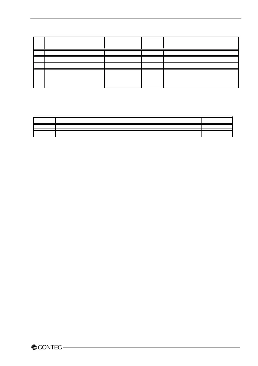
Table 3.1. Jumper List
Reference
page
JP1 - Selects BUS clock scale. 1-2 shorted --- Settings other than 1-2 are not allowed.
JP2 - Clear CMOS. 1-2 shorted --- Short 2-3 to clear CMOS.
JP4 - Sets RS-485 termination. 2-3 shorted 55
- Sets destination where BIOS
setup details will be saved.
1, 3, 4, and 8 OFF 45
- Sets up LCD. 2, 5, 6, and 7 ON 76
S1
Function Factory setting RemarksNo.
Table 3.2. Internal Connector List
Connector Reference page
CN15 Primary IDE connector (44pin, pin header) 81
M2 Expansion memory set (3.3V, 144pin SO-DIMM) 22
Function