5. Each Component Function
76 User’s Manual
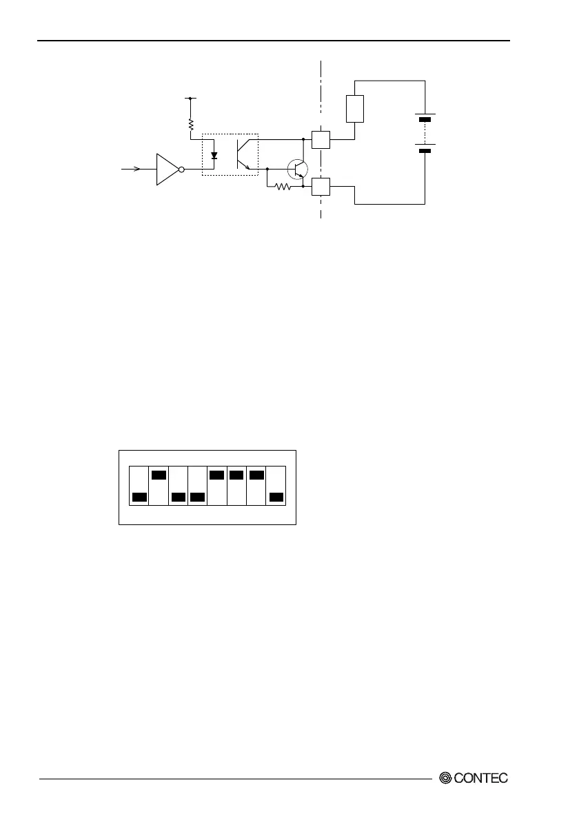
(PO 0~2)
(NCOM)
External power
(Max. 30VDC)
(External circuit)
RAS connector
PC817
Lard
510
Ω
4.7k
Ω
2N3904
Figure 5.22. Output Circuit
S1
S1's bit 2 selects whether to use CMOS or EEPROM for BIOS
setup details. For more information, see Chapter 4, "BIOS Setup."
S1's bits 5-8 are the LCD setting switch. For more information,
see section, "Liquid Crystal Display (LCD) Interface" in Chapter 5.
Do not modify the settings of S1 bits 1, 3 and 4 since they are used
by the system.
S1
ON
1 2 3 4 5 6 7 8
Figure 5.23. Factory Settings
Reset Switch
The BOX-PC is equipped with a hardware reset switch. To
prevent it from being pressed by mistake, the switch is designed to
be difficult to press. Use a pointed object to push the switch with.