5. Each Component Function
56 User’s Manual
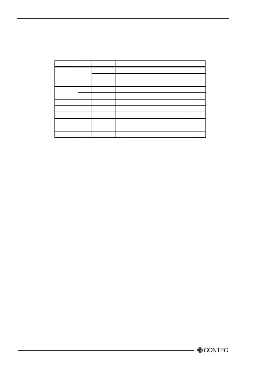
I/O Addresses and Instructions
The I/O addresses and instructions of COM1 are shown next.
Table 5.9. I/O Addresses
I/O address DLAB Read/Write
0 W Transmitter holding register THR
03F8H R Receive buffer register RBR
1 W Divisor latch register DLL
1 W Divisor latch register DLM
0 W Interrupt enable register IER
03FAH X R Interrupt ID register IIR
03FBH X W Line control register LCR
03FCH X W Modem control register MCR
03FDH X R Line status register LSR
03FEH X R Modem status register MSR
03FFH X R/W Scratch register SCR
DLAB (Divisor Latch Access Bit) : The value in bit 7 of the line control register
Register
03F9H