5. Each Component Function
User’s Manual
73
I/O Addresses and Instructions
* 4000h: General-purpose I/O
D6 D5 D4 D3 D2 D1 D0D7
PIO2 PIO1 PIO0
R/W
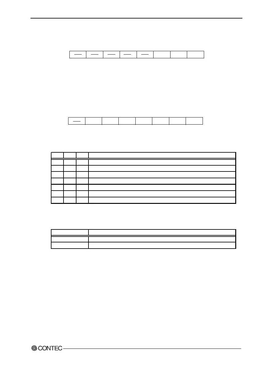
Figure 5.15. General-purpose Input Port (4000h)
R : Read data from PI0, PI1 and PI2.
W : Set data to be output to PO0, PO1 and PO2.
* 4001h (bit0-3): PI2/IRQ(14) event input control
WD_S0WD_S1 PO2_M PIM2 PIM1 PIM0RESET
D6 D5 D4 D3 D2 D1 D0D7
Figure 5.16. Event Input Control Port (4001h)
Table 5.23. PIM2-PIM0
PIM2 PIM1 PIM0
0 0 0 Inhibit the RAS connector's PI2/IRQ (14) signal interrupt to be set.
0 0 1 Input the RAS connector's PI2/IRQ (14) signal to NMI.
0 1 0 Input the RAS connector's PI2/IRQ (14) signal to IRQ5.
0 1 1 Input the RAS connector's PI2/IRQ (14) signal to IRQ7.
1 0 0 Input the RAS connector's PI2/IRQ (14) signal to IRQ9.
1 0 1 Input the RAS connector's PI2/IRQ (14) signal to IRQ10.
1 1 0 Input the RAS connector's PI2/IRQ (14) signal to IRQ11.
PI2/IRQ (14) interrupt input
Table 5.24. RESET: Reset Input Modes
RESET
0 Inhibit the remote reset input function of the RAS connector's PI2/IRQ (14) signal.
1 Use as the remote reset input function of the RAS connector's PI2/IRQ (14) signal.
PI2/IRQ (14)'s RESET input
Note!
A bit indicated with "rsv" is used by the system.
Do not modify the bit.