5. Each Component Function
80 User’s Manual
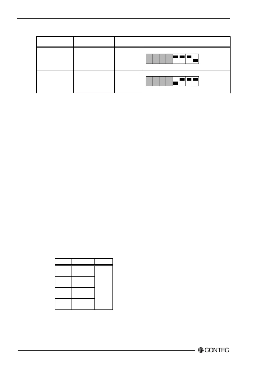
Table 5.28. LCD Connection List
SW1 settingsDisplay
12.1inch TFT with
a panel-mounting
touch panel
15inch TFT with
a panel-mounting
touch panel
Model
IPC-DT/L40S(PC)T
IPC-DT/H40X(PC)T
Display
SVGA
(800 x 600)
XGA
(1024 x 768)
ON
1 2 3 4 5 6 7 8
ON
1 2 3 4 5 6 7 8
S1-5 : ON
S1-6 : ON
S1-7 : ON
S1-8 : OFF
S1-5 : OFF
S1-6 : ON
S1-7 : ON
S1-8 : ON
* Factory settings
*
- A CRT (connected to the VGA connector) and an LCD can be
used simultaneously. However, the display area on the CRT is
the same as on the LCD.
- To use only the CRT, select CRT during BIOS setup (see Chapter
4).
Serial Interface for Touch Panel (Inside the LCD connector)
The BOX-PC is equipped with a serial port (Serial port C) to
communicate with a touch panel when an LCD equipped with a
touch panel is used. The I/O address, interrupt, or "not in use" can
be set with BIOS setup (see Chapter 4). (Do not set to the same
I/O address and interrupt as those of another device.)
Set to the same values as were set during installation of the touch-
panel driver software (either downloaded from the home page or
purchased separately).
A set of optional driver software and utility software:
IPC-SLIB-01 (provided on a CD-ROM)
(Windows 98 Second Edition, Windows NT 4.0, and Windows 2000
for Professionals)
Table 5.29. Serial Port C I/O Addresses and Interrupts
COM I/O address Interrupt
1 3F8h-3FFh
2 2F8h-2FFh
3 3E8h-3EFh
4 2E8h-2EFh
IRQ 3
IRQ 4
IRQ 5
IRQ 7
IRQ 9
IRQ 10
IRQ 11
IRQ 15
The BIOS defaults to the following factory settings:
Serial port C : COM3(3E8h-3EFh),IRQ7