Parameter
structure
Keypad and
display
Parameter x.00
Parameter
description format
Advanced parameter
descriptions
Serial comms
protocol
Electronic
nameplate
Performance
Menu 6
Digitax ST Advanced User Guide 89
Issue Number: 1 www.controltechniques.com
Only one stopping phase exists and the ready state is entered as soon as the single stopping action is complete. It should be noted that the stop
condition is detected when the speed feedback is below the zero speed threshold (Pr 3.05) for at least 16ms. If the speed is not stable it is possible
that the stop condition is not detected. In this case the system should be made more stable or the zero speed threshold should be raised.
If coast stop is selected the inverter is inhibited immediately when the run command is removed. If however, hold zero speed is also selected (Pr 6.08
= 1), then the inverter will be re-enabled to hold zero speed. The result is that the inverter is disabled for one sample and then enabled to ramp the
motor to a stop. Therefore if coast stop is required Pr 6.08 should be set to zero to disable hold zero speed.
If stop with ramp is selected the relevant ramp rate is used to stop the motor even if Pr 2.02 is set to zero to disable ramps.
The motor can be stopped with position orientation after stopping. This mode is selected with the position controller mode (Pr 13.10). When this mode
is selected Pr 6.01 has no effect.
0: dis
There is no mains loss detection and the drive operates normally only as long as the DC bus voltage remains within specification (i.e. >Vuv). Once the
voltage falls below Vuv a UV trip occurs and this will reset itself if the voltage rises again above Vuv Restart shown in the table below.
1: Stop
The speed reference is set to zero and the ramps are disabled allowing the drive to decelerate the motor to a stop under current limit. If the mains is
re-applied while the motor is stopping any run signal is ignored until the motor has stopped. If the current limit value is set at a very low level the drive
may trip UV before the motor has stopped. If the mains is reapplied the drive restarts after it reaches the ready state provided the necessary controls
are still active to initiate a start.
2: ride.th
The drive detects mains loss when the DC bus voltage falls below Vml
1
. The drive then enters a mode where a closed-loop controller attempts to hold
the DC bus level at Vml
2
. This causes the motor to decelerate at a rate that increases as the speed falls. If the mains is re-applied it will force the DC
bus voltage above the detection threshold Vml
3
and the drive will continue to operate normally. The output of the mains loss controller is a current
demand that is fed into the current control system and therefore the gain parameters Pr 4.13 and Pr 4.14 must be set up for optimum control. See
Pr 4.13 and Pr 4.14 on page 74 for set-up details.
The following table shows the voltage levels used by drives with each voltage rating.
* Vml
1
is defined by Pr 6.48. The values given in the table are the default values.
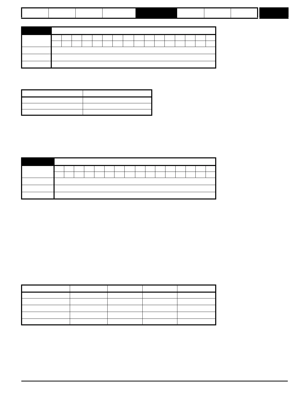
6.01 Stop mode
Coding
BitSP FI DETEVMDPNDRANCNVPTUSRWBUPS
1 111
Range 0 to 2
Default 2
Update rate Background read
Stopping Mode Action
0: Coast Inhibits the inverter
1: Ramp Stop with ramp
2: No ramp Stop with no ramp
6.03 Mains loss mode
Coding
BitSP FI DETEVMDPNDRANCNVPTUSRWBUPS
1 111
Range 0 to 2
Default 0
Update rate Background read
Voltage level 200V drive 400V drive 575V drive 690V drive
Vuv 175 330 435 435
Vml
1
205* 410* 540* 540*
Vml
2
Vml
1
- 10V Vml
1
- 20V Vml
1
- 25V Vml
1
- 25V
Vml
3
Vml
1
+ 10 Vml
1
+ 15 Vml
1
+ 50 Vml
1
+ 50
Vuv Restart 215 425 590 590