33
inverter enclosure. Covers may be required in the future if an
inverter or wirebox is to be removed during servicing (see
step 6,
(d) Figure 3-15). Tool required: No.2 Phillips head screwdriver
Step 4 Secure the wirebox to the main enclosure by using the M6x18
screws (4pcs) to fasten the wirebox. (see Figure 3-13). Tool
required: No.3 Phillips head screwdriver or 10mm Wrench,
torque value of 4 N.m (35.4in-lbs)
CAUTION:
M6X18 screws must
be properly fastened
to ensure electrical
bond.
Figure 3-13 Installation of the Wiring Box
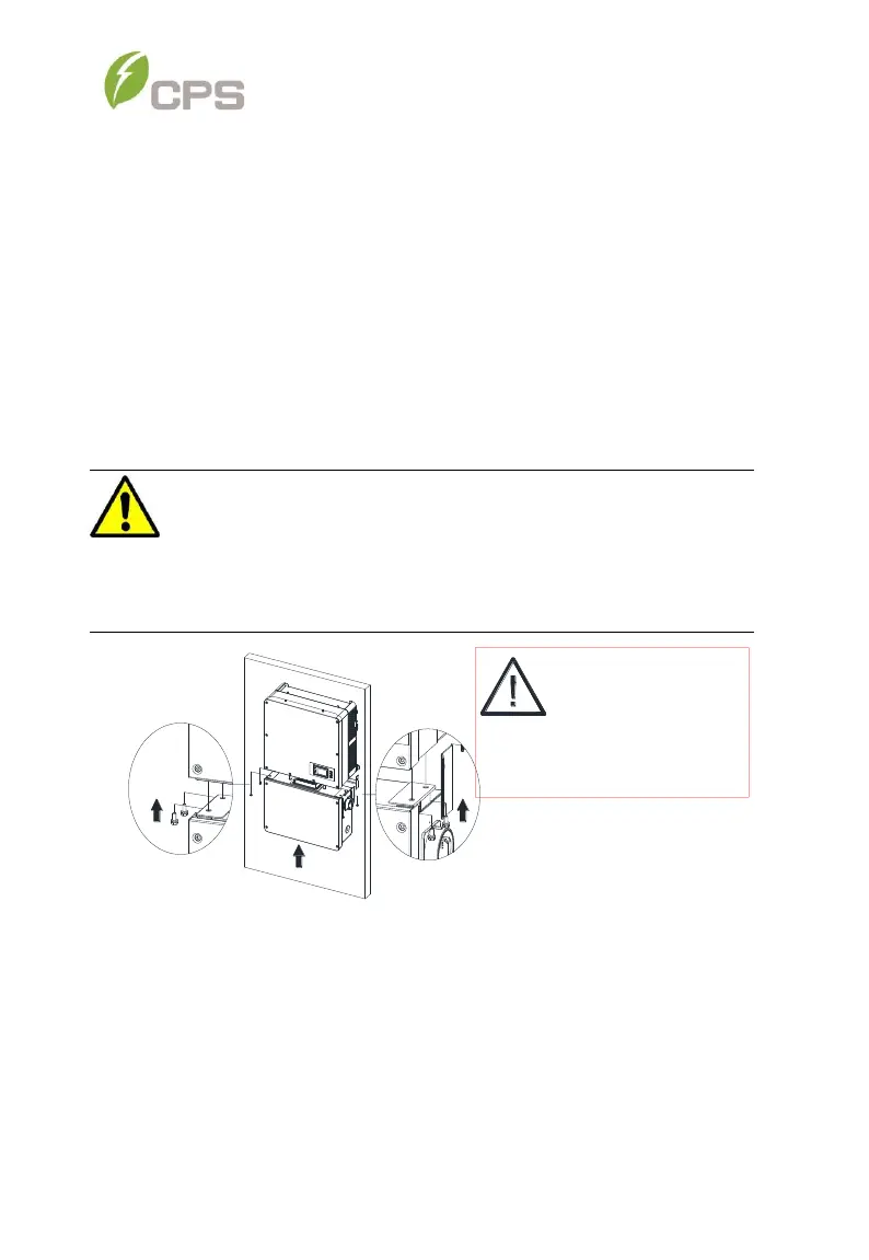
Step 5 Attach the main enclosure and the wiring box to the mounting
bracket with the M6x18 screws (6 pcs). (see Figure 3-14). Tool
required: No.3 Phillips head screwdriver, torque value of 4N.m
(35.4in-lbs)
WARNING:
Ensure the M6x18 screws (4pcs) installed in Step 4 above are
properly torqued and the area under the bolt-head is clear of paint.
This connection provides an electrical ground bond of the wirebox
to the upper/main enclosure.