103
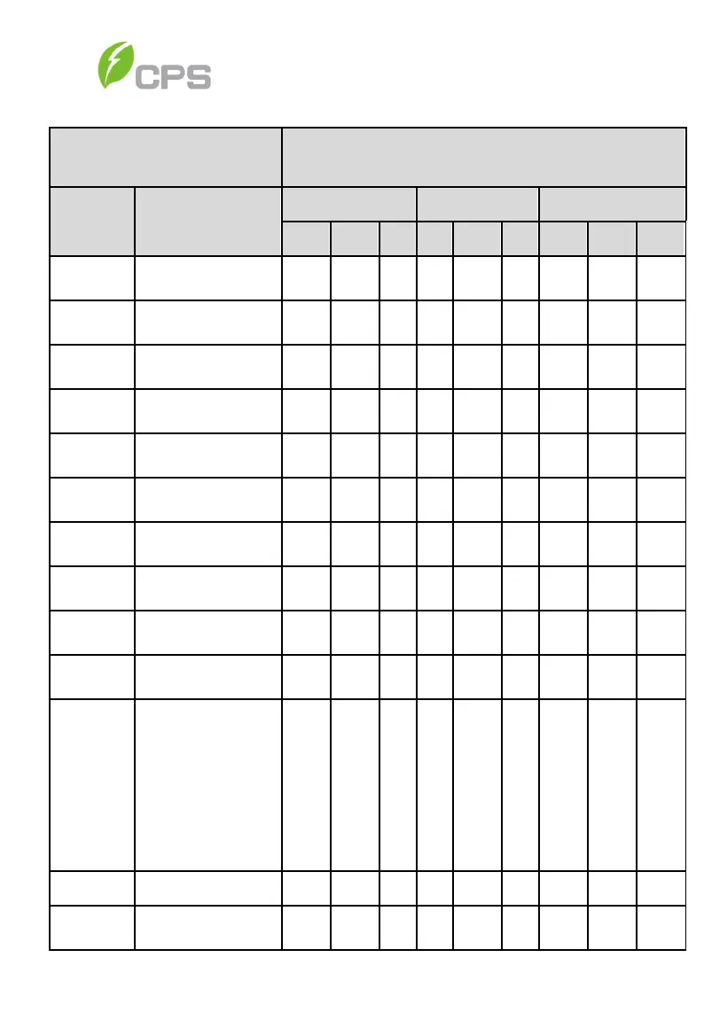
Table 6-10 Reactive Power Control (IEEE-1547, Rule21, and ISO-NE)
Grid Reactive Power
Derating
Setting Range
Parameter
name
Description
IEEE1547 Rule21 ISO-NE
Min Default Max Min Default Max Min Default Max
QuCurveU1
Voltage of Q(U) Curve point
1
100 107.9 110 100 103.3 110 100 107.99 110
QuCurveQ1
Reactive power of Q(U)
-66 0 66 -66 0 66 -66 0 66
QuCurveU2
Voltage of Q(U) Curve point
2
100 110 110 100 107 110 100 110 110
QuCurveQ2
Reactive power of Q(U)
-66 -50 55 -66 -30 66 -66 -50 66
QuCurveU1i
Voltage of Q(U) Curve point
1i
90 92.01 100 90 96.7 100 90 92.01 100
QuCurveQ1i
Reactive power of Q(U)
-66 0 66 -66 0 66 -66 0 66
QuCurveU2i
Voltage of Q(U)Curve point
2i
80 90 92 80 92 92 80 90 92
QuCurveQ2i
Reactive power of
-66 50 66 -66 30 66 -66 50 66
QuCurveTri
The trigger of Q(U)Curve 5 20 100 5 20 100 5 20 100
QuCurveUn
The end of Q(U)Curve 5 5 100 5 5 100 5 5 100
CtrMode
The control mode of
reactive power
0: Disable dispatch mode.
0 0 5 0 5 5 0 0 5
Percentage
Local Power Factor Setting
-66 0 66 -66 0 66 -66 0 66
PFSetValue Local Power Factor Setting
-1.0,
1.0
0.8,
-1.0,
0.950
0.8,
-1.0,
1
0.8,