56 • TST-902 Product Manual — Doc. 7750C
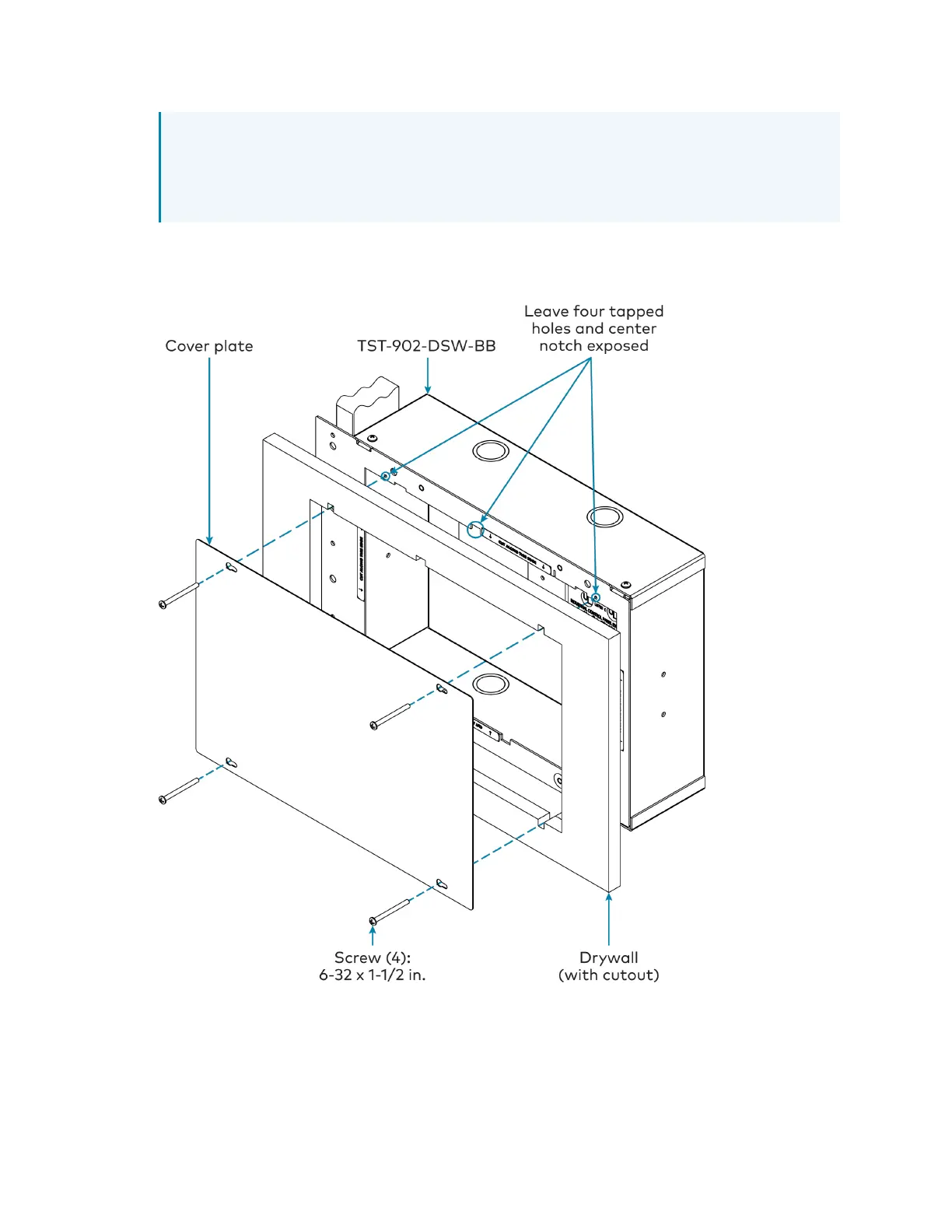
NOTE:The four tapped holes on the front of the back box must be exposed in order to
accept the TST-902-DSWmounting screws. These holes are located along the top and
bottom of the drywall opening. The notch at the top center of the back box must also
be exposed to accommodate the TST-902-DSWlocking latch.
8. (Optional)If required by local building codes, use the 6-32x1-1/2in. screws to install the
included cover plate over the back box. The cover plate should remain attached until the
TST-902-DSWis installed.
9. Remove the cover plate and 6-32x1-1/2in. screws (if used), and then install the
TST-902-DSWwall dock into the TST-902-DSW-BBas described in Install the
TST-902-DSW on page 47 with the 6-32x1-1/2in. screws.