IM 817-7 16 www.DaikinApplied.com
Unit Ventilator Installation
Before setting the unit ventilator in position, be sure that
eld-supplied electrical connections are in place, de-
energized and in accordance with the plans.
Move the unit ventilator into position against the wall
surface. Check to see that the unit ventilator is level
from end to end and back to front. Using a 4' level is
recommended. Leveling bolts are located at each end of
the front kickplate (Figure 34).
Figure 34: Leveling Legs Location
NOTICE
Face and Bypass damper set-up is required at start-up.
Failure to properly set-up Face and Bypass damper can result in
control problems and unit damage not covered by warranty. Refer
to Service Bulletin, UV-SB-106507312.
Figure 35: Setting The Unit Ventilator In Place
Remove
moldings
behind unit
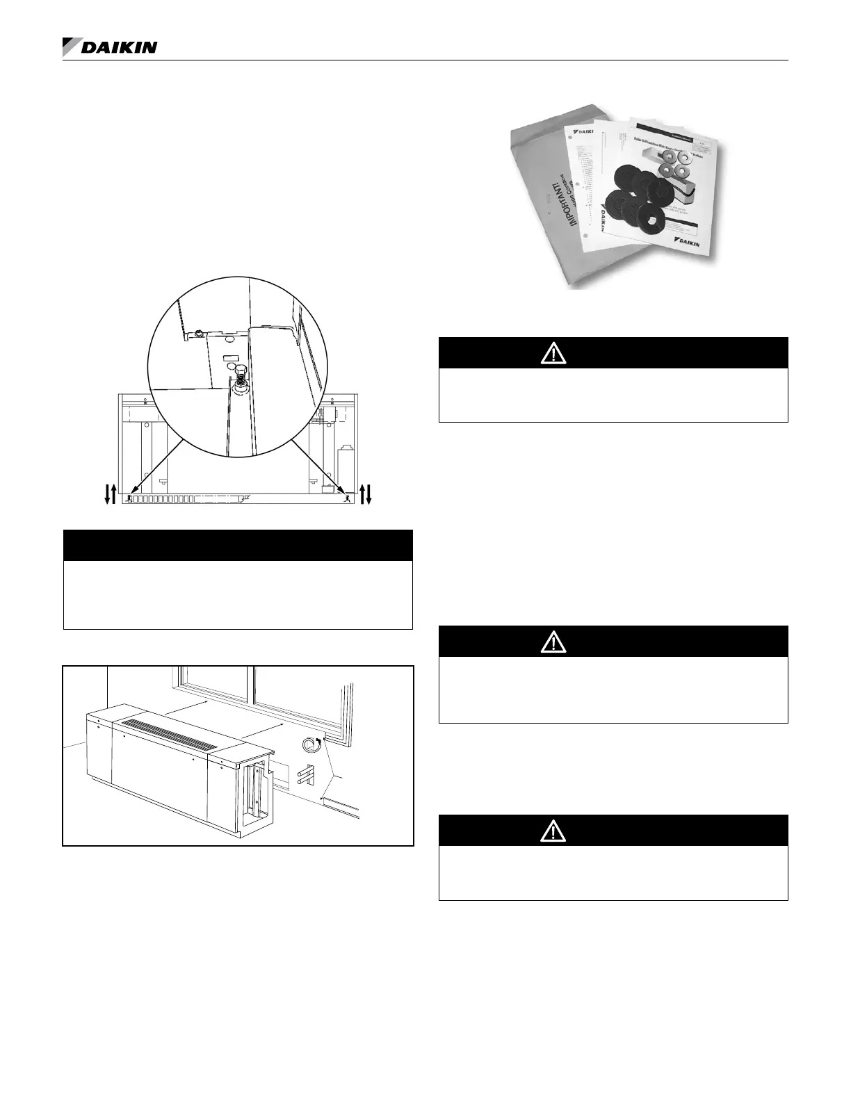
Refer to Figure 32 on page 15 and Figure 26 and Figure
27 on page 13 and attach the unit ventilator to the wall
through the four (4) mounting holes provided, using eld-
supplied fasteners appropriate to the wall construction and
the washers provided in the brown envelope with these
instructions (Figure 36). Envelope also contains allen
wrench to provide access to unit. Push the unit ventilator
tight to the wall structure so that the outdoor air seals are
compressed. Secure the wall fasteners to prevent the unit
ventilator from moving and tipping over.
Figure 36: Shipping Envelope Contents.
Make Piping Connections
CAUTION
Be sure the hot and chilled water supply and return system are
thoroughly ushed and cleaned before connecting piping to the
unit ventilator. Debris in the lines can damage the unit.
For All Systems
Be sure to install the control valve(s) on the correct unit
ventilator. Indiscriminate mixing of valves in the eld can
result in valves improperly sized for the desired ow rate,
which can result in poor operation and coil freezeups.
Install control valve so there is at least 2ʺ (51mm) minimum
clearance to remove the actuator from the valve body.
Be certain that the control valve is installed correctly,
with its orientation vertical. Valves should be installed at
least 5 degrees off center.
CAUTION
Be certain that the control valves are installed with the proper
port orientation to provide proper ow and fail safe operation.
Incorrect installation can result in improper unit operation, and/or
the possibility of coil freeze-up.
With future servicing considerations in mind, use
standard, eld-supplied shutoff valves and union
connections; this permits easy removal of the coil or
control valve if servicing is required.
WARNING
While brazing, have an extinguisher readily available. Wear
appropriate eye and hand protection. Ensure all areas with shared
ventilation have ample fresh air ventilation.
Proper ventilation is required for brazing. When brazing,
be sure to protect unit ventilator components from
overheating damage (melting insulation, also damage to
valves, wiring, electronics, sensors, etc.).
Before lling, be sure to ush all piping adequately so that
all debris is removed. Debris can prevent proper valve
operation, resulting in overheating, overcooling, etc.