www.DaikinApplied.com 47 IM 817-7
MicroTech Wall Mounted Sensor
WARNING
Rigorously adhere to eld wiring procedures regarding proper
lockout and tagout of components.
WARNING
To avoid electrical shock, personal injury or death:
1. Installer must be qualied, experienced technician.
2. Disconnect power supply before installation to prevent
electrical shock and damage to equipment.
3. Make all connections in accordance with electrical wiring
diagrams, and in compliance with national and local codes.
Use copper conductors only.
4. Do not exceed ratings of the device. This is a low voltage
device: Never apply more than 12VAC/VDC to any lead or
damage will result.
5. Avoid locations where excessive moisture, corrosive fumes,
or vibrations are present.
Note: Avoid placing wall sensor near drafty areas such as doors
or windows. Avoid external walls, or dead spots near
exposed columns. Avoid direct sunlight on wall sensor.
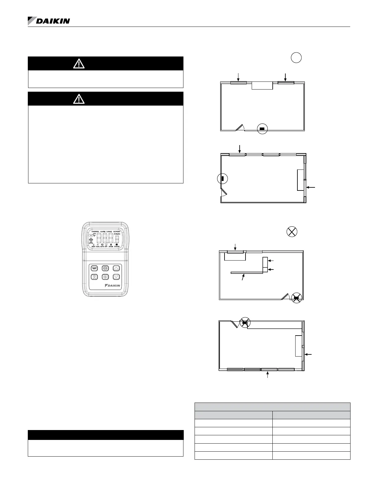
Figure 106: Wall Mounted Temperature Sensor
When Using A Remote Temperature
Sensor
If a decision is made to use a Wall Mounted Temperature
Sensor instead of the unit mounted room air sensor then
placement of the Remote Wall Mounted Temperature
Sensor is critical for proper room temperature sensing (see
Figure 107 and Figure 108). The UVC is capable of using
one of four remote wall mounted temperature sensors.
It is recommended that additional wires be pulled to
compensate for potential wire breakage or future options.
• 6-Button Digital Adustable Sensor (PN 910247458) 8-wires
• 4-Button Digital Adustable Sensor (PN 910247448) 6-wires
• The Basic Sensor with setpoint adjustment (PN
910247453) 4-wires
• The Basic Sensor (PN 910247450) 3-wires
For sensor terminal wiring details see the installation manual specic
to the sensor being used.
NOTICE
Figure 107: Correct Wall Sensor Locations
Window Exposure
Window Exposure
Window Exposure
Interior Wall
Interior Wall
Interior Wall
Interior Wall
Unit
Unit
= Correct Sensor Location
Window Exposure
Figure 108: Incorrect Unit and Wall Sensor Locations
= Incorrect Sensor Location
Window Exposure
Interior Wall
Interior Wall
Window Exposure
Unit
Unit
Interior Wall
Interior Wall
Window Exposure
Cubicle Wall
Shelving
File Cabinet
Shelving
Table 36: Max Sensor Wire Length and Gauge
Maximum sensor wire length for less than 1°F error
Gauge Length
14 AWG 800 ft. (244 m)
16 AWG 500 ft. (152 m)
18 AWG 310 ft. (94 m)
20 AWG 200 ft. (61 m)
22 AWG 125 ft. (38 m)