www.DaikinApplied.com 39 IM 817-7
WARNING
Hazardous Voltage! Disconnect all electric power including
remote disconnects before servicing. Failure to disconnect power
before servicing can cause severe personal injury or death.
Determining System Superheat
After the subcooling has been determined, check system
superheat.
1. Determine required superheat from superheat range,
Table 33.
2. Measure suction line temperature 6 inches from
service valve.
3. Measure suction line pressure at service valve and
determine saturated suction temperature from Table 32.
4. Subtract saturated suction temperature from
measured temperature to obtain superheat.
5. Refer to Table 33 and adjust charge as required for
correct superheat at ambient conditions.
NOTICE
Each time that charge is added or removed from the system, allow
the system to run approximately 20 - 30 minutes before pressure
and temperature readings are taken and superheat calculations
made.
NOTICE
If system hunting occurs or subcooling is reduced, it may be
necessary to adjust TXV to obtain correct superheat.
Table 32: Saturated Temperature - Pressure Chart
(ºF) R410A-PSIG (ºF) R410A-PSIG (ºF) R410A-PSIG
32 101.1 44 127.7 80 235.8
33 103.2 45 130.2 85 254.7
34 105.2 46 132.6 90 274.5
35 107.4 47 135.1 95 295.5
36 109.5 48 137.5 100 317.6
37 111.7 49 140.1 105 340.9
38 113.9 50 142.6 110 365.4
39 116.2 55 147.0 115 391.2
40 118.4 60 170.1 120 418.3
41 120.7 65 185.2 125 446.9
42 123.0 70 201.1 130 476.8
43 125.4 75 218.0 140 541.4
Table 33: Superheat Range
Outdoor
Ambient
Indoor Coil Air Inlet Temp. DB/WB (50% RH)
75/63 80/67 85/71
105 * * 8-10
100 * 3-5 9-11
95 * 5-7 11-13
90 * 9-11 13-15
85 5-7 10-12 15-17
80 8-10 12-14 18-20
75 10-12 15-17 21-23
70 13-15 19-21 24-26
65 15-17 21-23 26-28
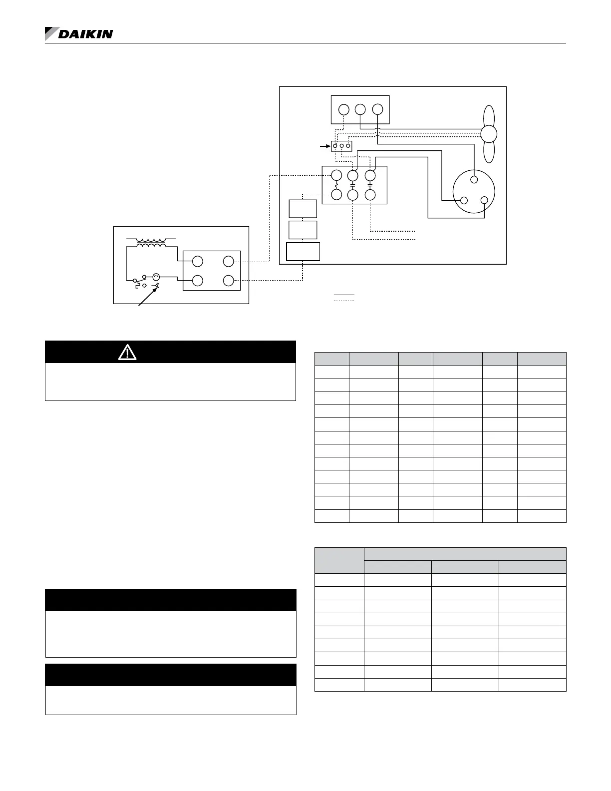
Figure 98: Typical Unit Ventilator/Condensing Unit Wiring Diagram
24V
24V
Compressor
Compressor
Contactor
Capacitor
Head
Pressure
Controller
(Optional)
Fan
Motor
High
Pressure
Switch
Low
Pressure
Switch
TDR = Time Delay Relay
TB = Terminal Block
T4
2
3
1
Rec3
Line Vo ltage
Factory Wired
Field Wired (By Others)
TDR or TB
Low Ambient
Temp. Switch
To controls by others, to energize condensing unit normally
open contact.
T1
T2
L2
L1
L2
L1
Typical Condensing Unit
Typical Unit Ventilator Interface