www.DaikinApplied.com 19 IM 817-7
Coil Headers, Locations (continued)
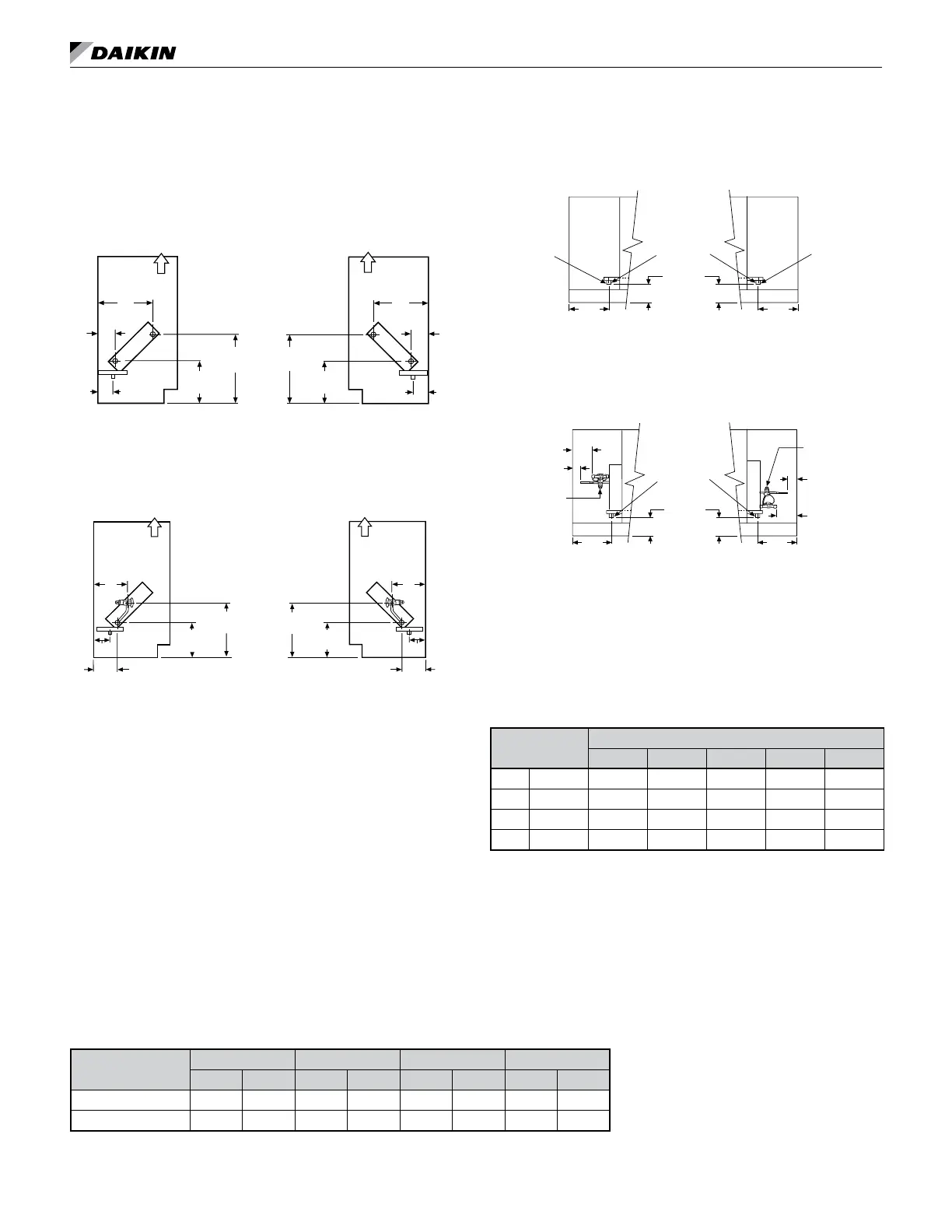
Cooling Only Units
Figure 45: Chilled Water Only Unit (Coils V, S, W)
Note: This arrangement available on AVV and AVS units only.
R
S
J
A
B
B
8-1/2"
(216mm)
13-3/4"
(349mm)
J
A
13-3/4"
(349mm)
8-1/2"
(216mm)
Air Flow
Right HandLeft Hand
R
S
S = Supply
R = Return
Figure 46: Direct Expansion Cooling Only Unit (Coils G)
Note: This arrangement available on AVV units only.
LL
SL
J
D
C
7-1/4"
(184mm)
Air Flow
11-3/4"
(299mm)
Air Flow
Cooling (Left Hand) Cooling (Right Hand)
LL = Liquid Line
SL = Suction Line
LL
SL
J
D
C
7-1/4"
(184mm)
11-3/4"
(299mm)
Condensate Drain Locations
Figure 47: Condensate Drain
7/8"(22 mm)
O.D. Drain
7/8"(22 mm)
O.D. Drain
Condensate
Left Hand Right Hand
Drain
11"
(279 mm)
11"
(279 mm)
Front View of End Compartment
(Without End Panels)
4-3/4"
(121 mm)
Figure 48: Condensate Drain and DX Coil Connections
7/8"(22 mm)
O.D. Drain
11"
(279 mm)
11"
(279 mm)
Front View of End Compartment
(Without End Panels)
4-3/4"
(121 mm)
SL
SL
LL
LL
LL = Liquid Line
SL = Suction Line
5-1/4" (133 mm)
1-1/2" (38 mm)
5-1/4" (133 mm)
1-1/2" (38 mm)
TX Valve
TX Valve
Left Hand Right Hand
Notes:
1. All coils have same end supply and return connections.
2. Steam coils have a factory installed pressure equalizing valve and a 24ʺ
(610mm) long pressure equalizing line which terminates in a 1⁄2ʺ M.P.T. tting.
3. Steam/hot water connections may be same end as cooling coil connections,
but they are recommended to be opposite end to facilitate piping. (Must be
opposite end when using Daikin controls.)
4. Cooling condensate drain pan is shipped sloped down towards the cooling
coil connections but is eld reversible.
5. Electric heating coil power connections are right end only. Junction box has
1ʺ(25mm) and 2ʺ (51mm) (trade size) knockouts, 10-1⁄2ʺ (267mm) from right
end of the unit.
6. Coil stubs are 7⁄8ʺ I.D. (female) and terminate 9ʺ (229mm) from the end of
the unit.
7. Steam coils are 1-1⁄8ʺ female (sweat) connections and terminate 9ʺ (229mm)
from the end of the unit.
8. DX coils (G) have O.D. sweat connections. Interconnecting tube by others.
See Table 5 for correct tubing size.
Table 4: Coil Connection Dimensions For Lettered Values
Unit Depth
Dimensions
A B C D J
in. 16-5/8 3-3/4 12-1/4 4-7/8 7-3/4 3
mm 422 95 311 124 198 76
in. 21-7/8 9 17-1/2 10-1/8 13 8-1/4
mm 556 229 445 257 330 210
Table 5: DX Coil (G) Connection Tubing
Unit Series
S07 S10 S13 S15
in mm in mm in mm in mm
Suction Line OD: 3/4 19 3/4 19 7/8 22 7/8 22
Liquid LIne OD: 1/4 6.35 1/4 6 3/8 10 3/8 10