IM 817-7 62 www.DaikinApplied.com
Controls by Others – Electrical
Connections
WARNING
Rigorously adhere to eld wiring procedures regarding proper
lockout and tagout of components.
WARNING
To avoid electrical shock, personal injury or death:
1. Installer must be qualied, experienced technician.
2. Disconnect power supply before installation to prevent
electrical shock and damage to equipment.
3. Make all connections in accordance with electrical wiring
diagrams, and in compliance with national and local codes.
Use copper conductors only.
4. Do not exceed ratings of the device. This is a low voltage
device: Never apply more than 12VAC/VDC to any lead or
damage will result.
5. Avoid locations where excessive moisture, corrosive fumes,
or vibrations are present.
See Table 35 on page 46, Figure 121 through Figure
123 and the job-specic electrical drawings before
proceeding with eld power and control wiring. See also
the wiring diagram provided on the unit ventilator right
front access panel.
Unit ventilators equipped with an optional electric
heating coil have electric heating coil power connections
at right end only.
Procedure
1. Provide power supply to right end compartment to
match unit nameplate.
CAUTION
Use copper conductors only. Use of aluminum conductors may
result in equipment failure and overheating hazards. All wiring in
right hand compartment must be class 1.
2. Wire leads provided from unit ventilator electric
connection box to load side of unit power switch
(switch provided by Daikin). The junction box has
1"(25mm) and 2"(51mm) knockouts, located 10-
1/2"(267mm) from right end of unit.
3. Provide ground wire from grounding screw in switch
junction box to switch ground terminal.
4. Wire eld power supply to line side of unit power
switch. Wire ground conductor to switch ground
terminal.
5. Mount unit power switch in switch junction box and
install switch cover plate (provided).
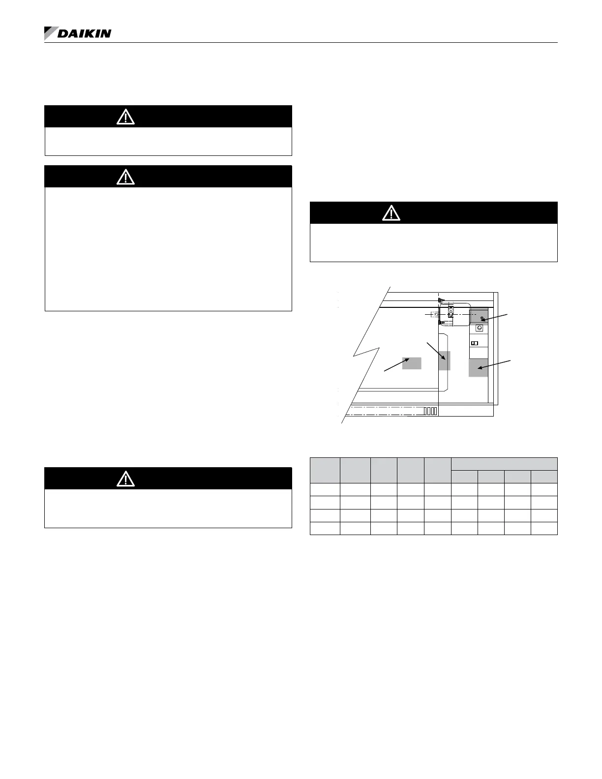
6. On units with electric heat, the 2 pole unit power
switch is replaced by a 3 pole switch and is mounted
in the location as shown in Figure 121. (A) shows
switch location for valve control units and (B), (C) and
(D) show location for Face & Bypass control units.
(B) is for 208, 230 and 265 volt units. (C) shows
location for 460 volt units. Also, on electric heat units
with controls by others, wiring to the eld mounted
controller is done in the left end compartment. See
specic wiring diagram for details. The unit comes
with wiring that requires relay controls by others
CAUTION
It is the responsibility of the Automatic Temperature Control
supplier to ensure that the proper electric heat control components
are installed, and operate correctly to protect the unit.
Figure 121: Electric Heat Unit Power Switch Locations
A
B
C
D
Table 41: Floor AV Electrical Data/Motor Data and Unit
Amp without Electric Heat
Unit
Series
CFM
(Nom.)
L/s
Motor
HP
Watts
Unit Current #
115V 208V 230V 265V
S07 750 354 1/4 216 2.2 1.2 1.1 1.0
S10 1000 472 1/4 277 2.8 1.6 1.4 1.3
S13 1250 590 1/4 335 3.3 1.9 1.7 1.5
S15 1500 708 1/4 445 4.4 2.6 2.3 2.0
# Amps at unit voltage, 60 Hz, single phase
Note: See Electric Heating on page 65, Table 40 on page
56 and Table 41.
 Loading...


