www.DaikinApplied.com 23 IM 817-7
Typical Valve Packages
The optional factory-supplied Daikin Control Valve(s) for
water applications are either 2-way or 3-way type, and
are shipped separate from the unit ventilator itself to help
avoid shipping damage to the piping of the connection
stub from the weight of the valve, and to provide the
installer with maximum exibility in making the eld
piping connection. Before proceeding, see Figure 69
through Figure 92 as applicable, as well as the job-
specic piping drawings.
Notes:
1. See label furnished on 2-way valve to determine direction of ow through the
valve.
2. Adhere to the port orientation shown for the 3-way valve.
3. For hot water applications and chilled water/hot water (2-pipe) applications,
the 2-way valve furnished is normally piped open to the coil; the 3-way valve
is piped normally open to the coil.
4. For chilled water applications, the 2-way valve furnished is normally piped
closed to the coil; the 3-way valve is piped normally closed to the coil.
5. The 3-way valve is generally selected for diverting water back to the return
main, where a constant pump head pressure is required.
6. All water coil stubs are 7/8” I.D. female sweat. Coil connections terminate 9”
(229mm) from the end of the unit. Hot water connections may be same end as
cooling coil connections, but are recommended to be at opposite ends from
each other. When using MicroTech controls, they must be at opposite ends.
Face & Bypass End of Cycle Valves
2-Way End of Cylce Valve
When piping the 2-Way End of Cycle valve, refer to label
to determine the direction of ow. The valve should be
installed so that there is a 2” (51mm) minimum clearance
to remove the actuator from the valve body. Provide
unions for removal of unit coil and/or control valve as
a future service consideration. Hot water connections
may be same end as cooling coil connections, but are
recommended to be opposite end to facilitate piping.
When using MicroTech® controls, they must be opposite
end. The End of Cycle valve accessory must be eld
installed on the unit for which it was selected.
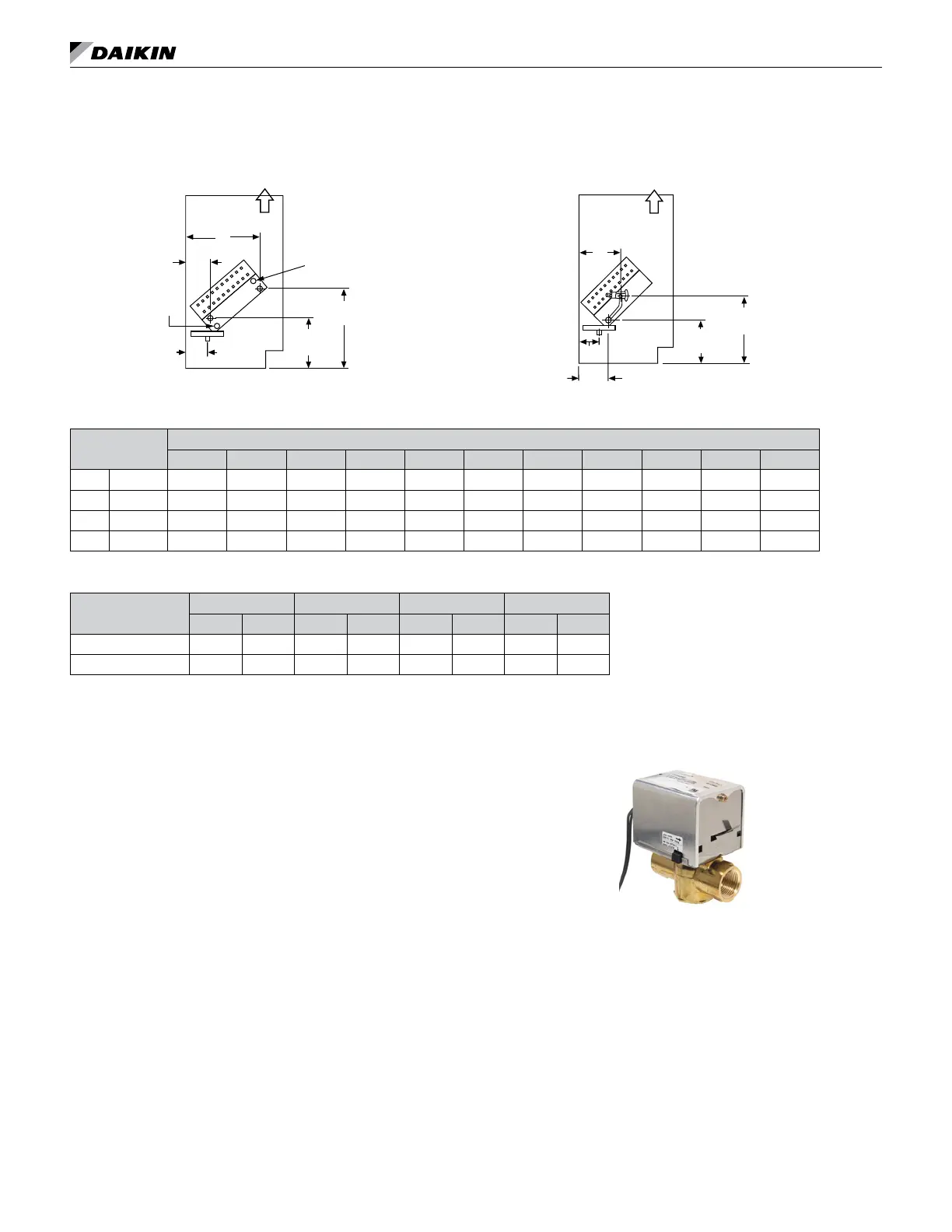
Chilled Water and Electric Heating Coils
Figure 67: Chilled Water (1st Position) and Electric Heating
(Cooling Coils V[5], S[6], W[7]), (Heating Coils 12, 13)
R
S
13-3/4"
(350mm)
A
B
J
8-1/2"
(216mm)
Air Flow
Vent
CW
Direct Expansion and Electric Heating Unit
Figure 68: Direct Expansion (1st Position) and Electric
Heating (Cooling Coils G[9]), (Heating Coils 12, 13)
LL = Liquid Line
SL = Suction Lin
LL
SL
J
D
C
7-1/4"
(184mm)
Air Flow
11-3/4"
(299mm)
Table 8: Coil Connection Dimensions For Lettered Values
1
Unit Depth
Dimensions
A B C D E F G H I J K
in. 16-5/8 3-3/4 12-1/4 4-7/8 7-3/4 1-5/8 10-1/8 2-3/4 2-7/8 5-5/8 3 5
mm 422 95 311 124 198 41 257 70 73 143 76 127
in. 21-7/8 9 17-1/2 10-1/8 13 6-7/8 15-3/8 8 8-1/8 10-7/8 8-1/4 10-1/4
mm 556 229 445 257 330 175 391 203 206 276 210 260
Table 9: Direct Expansion (DX) Coil G[9] Connection Tubing
Unit Series
07 10 13 15
in mm in mm in mm in mm
Suction Line OD: 3/4 19 3/4 19 7/8 22 7/8 22
Liquid LIne OD: 1/4 6.35 1/4 6 3/8 10 3/8 10