IM 817-7 24 www.DaikinApplied.com
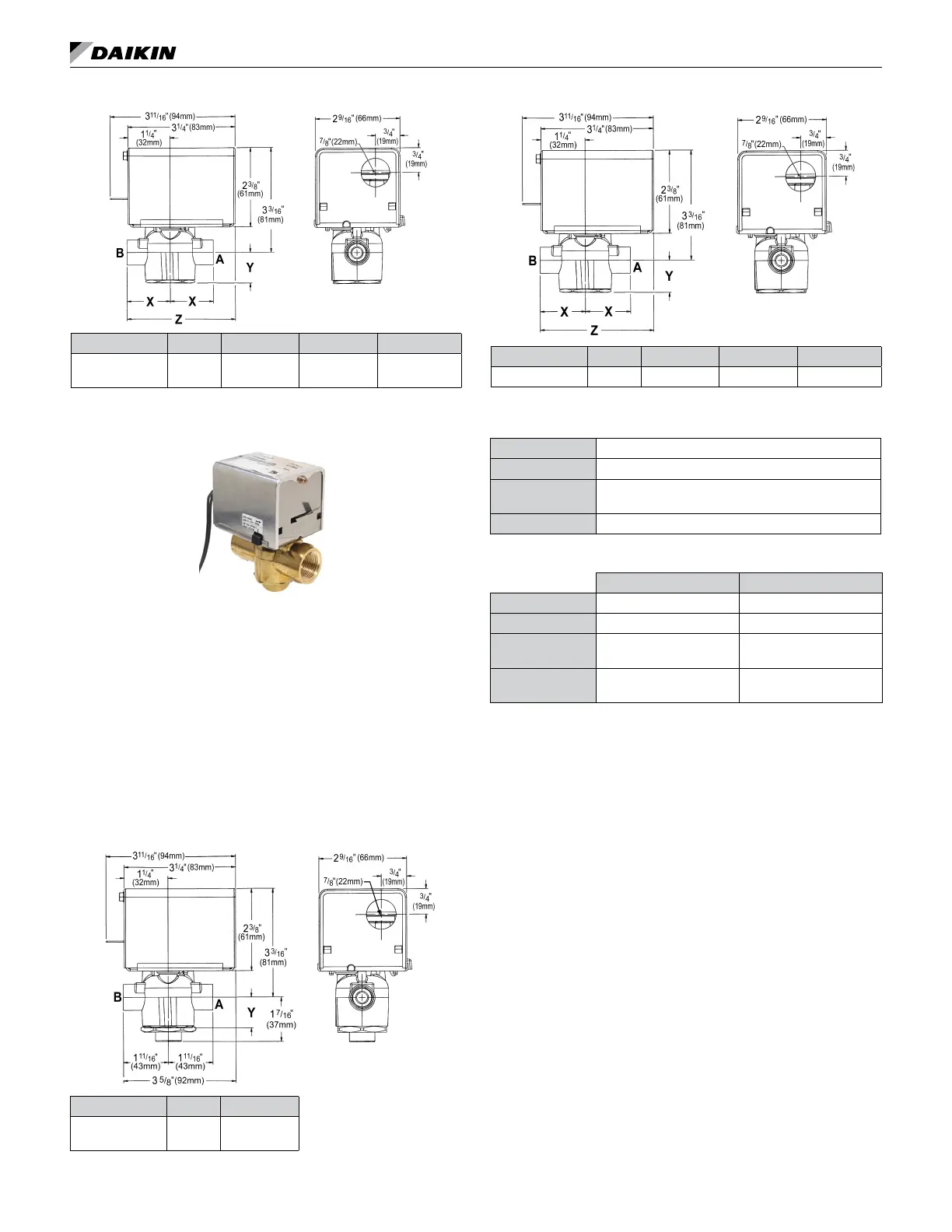
Figure 69: 2-Way EOC Valve Dimensions
Connection Cv X Y Z
3/4" (19mm)
FNPT
7.5
1
11
/16"
(43mm)
15
/16" (24mm) 3⅝" (92mm)
3-Way End of Cylce Valve
When piping the 3-Way End of Cycle valve, refer to label
to determine the direction of ow. The valve should be
installed so that there is a 2” (51mm) minimum clearance
to remove the actuator from the valve body. Provide
unions for removal of unit coil and/or control valve as
a future service consideration. Hot water connections
may be same end as cooling coil connections, but are
recommended to be opposite end to facilitate piping.
When using MicroTech® controls, they must be opposite
end. The End of Cycle valve accessory must be eld
installed on the unit for which it was selected.
Figure 70: 3-Way EOC Valve Dimensions
Connection Cv Y
3/4" (19mm)
FNPT
5.0
15
/16" (24mm)
Figure 71: 2-Way EOC Steam Valve Dimensions
Connection Cv X Y Z
1" (25mm) FNPT 8.0 1⅞" (47mm) 1" (25mm) 3
11
/16" (94mm)
Table 10: EOC Actuator Specifications
Control 2 Position
Electrical 24 VAC, 50/60 Hz
Stroke
Power Stroke 9 to 11 seconds
Spring return 4 to 5 seconds
Ambient 32°F to 125°F (0°C to 52°C)
Table 11: F&BP EOC Valve Body Specifications
2-Way Valve 3-Way Valve
Connections 3/4" FNPT, 1" FNPT 3/4" FNPT
Static Pressure 300 psi (2100 kPa) 300 psi (2100 kPa)
Close-Off Pressure
13 & 15 psi
(90 & 103 kPa)
13 psi (90 kPa)
Temperature
32°F to 200°F
(0°C to 93°C)
32°F to 200°F
(0°C to 93°C)