IM 817-7 46 www.DaikinApplied.com
MicroTech Unit Electrical
Connections
DANGER
Do not force adjustment stem of TXV. When adjusting superheat
To avoid electrical shock, personal injury or death, be sure that
eld wiring complies with local and national re, safety, and
electrical codes, and voltage to the system is within the limits
shown in the job-specic drawings and unit electrical data plate(s)
WARNING
Power supply to unit must be disconnected before making eld
connections. To avoid electrical shock, personal injury or death,
be sure to rigorously adhere to eld wiring procedures regarding
proper lockout and tagout of components.
See Table 35, Figure 104, Figure 105 and the job-
specic electrical drawings before proceeding with eld
power and control wiring. See also the wiring diagram
provided on the unit ventilator right front access panel.
Unit ventilators equipped with an optional electric
heating coil have electric heating coil power connections
at right end only.
Procedure
1. Provide power supply to right end compartment to
match unit nameplate.
CAUTION
Use copper conductors only. Use of aluminum conductors may
result in equipment failure and overheating hazards. All wiring in
right hand compartment must be class 1.
2. Wire leads provided from unit ventilator electric
connection box to load side of unit power switch
(switch provided by Daikin). The junction box has
1"(25mm) and 2"(51mm) knockouts, located 10-
1/2"(267mm) from right end of unit.
3. Provide ground wire from grounding screw in switch
junction box to switch ground terminal.
4. Wire eld power supply to line side of unit power
switch. Wire ground conductor to switch ground
terminal.
5. Mount unit power switch in switch junction box and
install switch cover plate (provided).
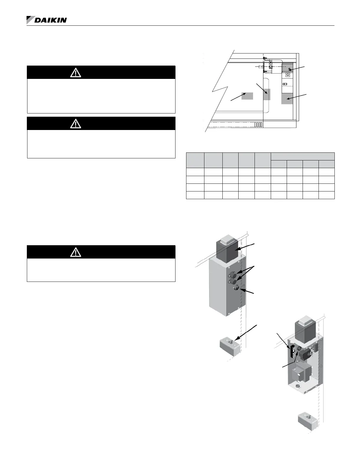
6. On units with electric heat, the 2 pole unit power switch
is replaced by a 3 pole switch, and is mounted as
shown on Figure 104. (A) shows switch location for
valve control units and (B), (C) and (D) show location
for Face & Bypass control units. (B) is for 208, 230 and
265 volt units. (C) shows location for 460 volt units.
Figure 104: Electric Heat Unit Power Switch Locations
A
B
C
D
Table 35: Floor AV Electrical Data/Motor Data and Unit
Amp without Electric Heat
Unit
Series
CFM
(Nom.)
L/s
Motor
HP
Watts
Unit Current #
115V 208V 230V 265V
S07 750 354 1/4 164 1.8 1.0 0.9 0.8
S10 1000 472 1/4 244 3.1 1.7 1.5 1.3
S13 1250 590 1/4 306 3.5 1.9 1.8 1.5
S15 1500 708 1/4 334 3.7 2.0 1.8 1.6
# Amps at unit voltage, 60 Hz, single phase
Note: See Electric Heating on page 65,Table 40 and Table 41.
Figure 105: Electric Connection Box and Junction Box
Located in Right End Compartment
Auto Transformer
Fuses
High-Med.-Low-Off Motor Speed Switch
Switch Junction Box
Terminal Strip
Electric Power Wire Opening
in Back of Box