www.DaikinApplied.com 45 IM 817-7
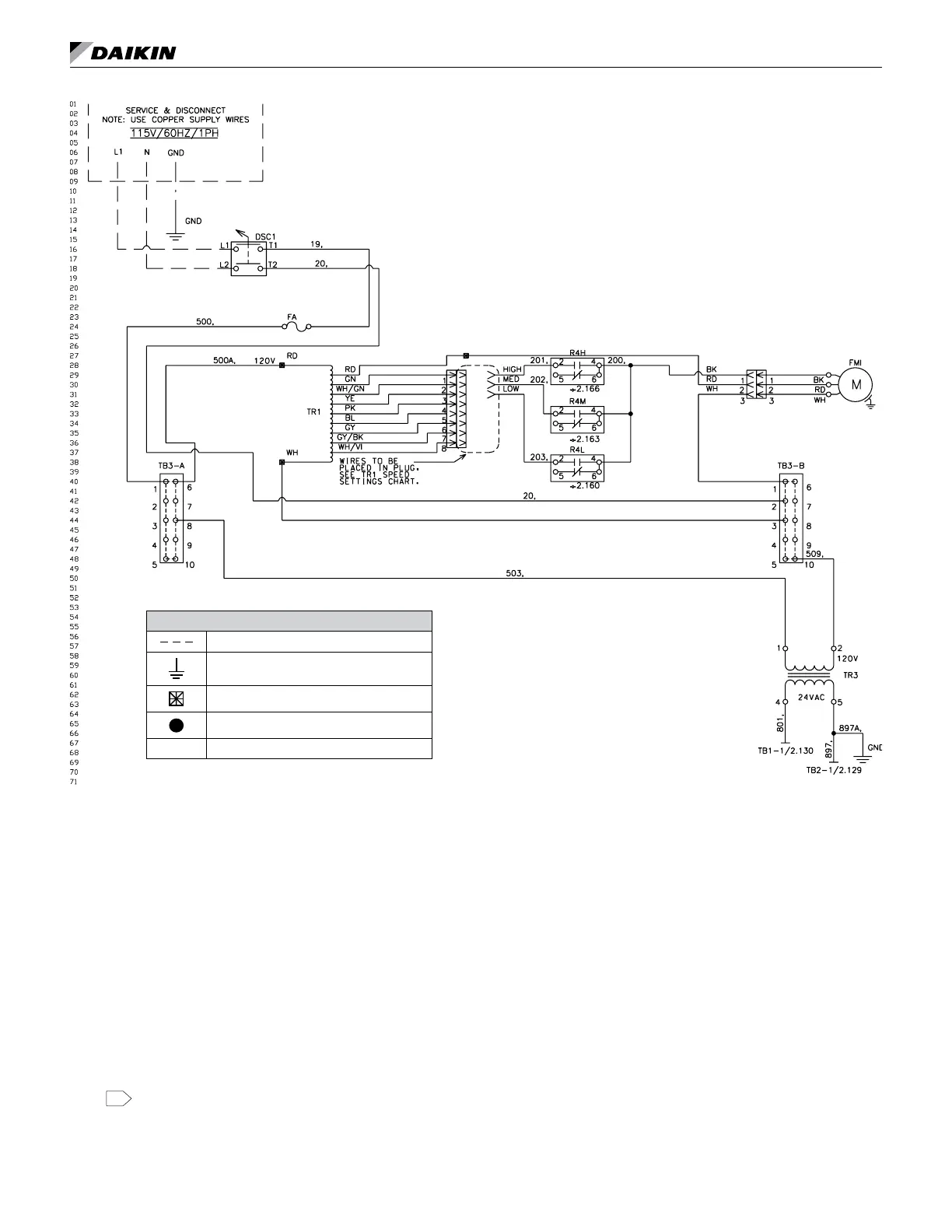
Typical MicroTech Wiring Diagram – Service and Disconnect, 115Volt / 60Hz / 1 Phase
Legend - Symbols
Accessory or eld mounted component
Ground
Wire nut / splice
Overlap point - common potential wires
L1/1.20 Wire link (wire link ID / page # . line #)
Table 34: Legend for Typical MicroTech Wiring
Symbol Description Symbol Description Symbol Description
A1 Actuator- Outdoor Air OH1 Thermostat - Overheat MCB Main Control Board
A2 Actuator- Face & Bypass OH2 Thermostat - Overheat IH Sensor - Indoor Humidity
C1 Compressor Contactor OHM E.H. Man Reset - Overheat Stat OH Sensor - Outdoor Humidity
CAP1 Capacitor Run PL1 LED Occupancy / Fault Status CO2 Sensor - Indoor Air CO2
CEH1-3 Electric Heat Contactor R1-R3 Relay Electric Heat (Backup) DCS Switch - Unit Power
DF Dead Front Switch R10-R12 Relay – Electric Heat TB1 Terminal Block - 24VAC+
F1A/F1B Fuse - Compressor R4H Relay – Fan High Speed TB2 Terminal Block – 24VAC Gnd
F2A/F3C Fuse - Electric Heat R4M Relay– Fan Medium Speed TB3 (A, B) Terminal Block – Main Power
FA/FB Fuse– Control, Load R4L Relay– Fan Low Speed TBE Terminal Block - Electric Heat
FC/FD Fuse– Control, Transformer R32 Relay - Drain Pan Heater TR1 Transformer - Motor Speed
HP High Pressure Switch R28 Relay - Outdoor Motor Air TR3 Transformer - 208 / 230V-24V, 75VA
EH1-6 Heater - Electric RV Reversing Valve TR4 Transformer - 460V–230V
EH10 Heater - Outdoor Drain Pan RAT Sensor - Room Air Temperature TR5 Transformer - 208 / 230V-24V
FMI Motor - Room Fan DAT Sensor - Discharge Air Temperature V1 Valve - Heat EOC (Accessory)
CP1 Motor Compressor 2-Stage OAT Sensor - Outdoor Air Temperature V2 Valve - Cool EOC (Accessory)
FMO Motor Outdoor Air ICT Sensor - Indoor DX Coil Temperature VH Valve - Heat (Accessory)
NTWK Network Connection OCT Sensor - Outdoor DX Coil Temperature VC Valve - Cool (Accessory)
Notes: 1. All electrical installation must be in accordance with national and local electrical codes and job wiring schematic.
. External wiring options - see IM for the different congured options, wiring to be minimum 18 gauge, 90°C.
3. EC motors are factory programmed for specied air ow. Contact Daikin Applied for replacement.
4. Cap extra wire. Switch wire 42A to red wire for 208V operation.
5. Switch wire 509 to terminal 2 for 208V operation.
6. Devices in legend may or may not be on unit.
2.