IM 817-7 36 www.DaikinApplied.com
Condensate Piping:
Daikin cooling unit ventilators are designed for
condensate removal into a condensate disposal
system. Do not connect the unit drain connection so
that condensate exits to the outside and/or is exposed
to freezing temperatures. Installer is responsible for any
damage that might be caused from freezing condensate.
In applications with an end compartment auxiliary drain
pan, see the installation instructions shipped with the
auxiliary drain pan itself.
Direct-Expansion (DX) R-410 Piping
DX coils have O.D. sweat connections. Interconnecting
tubing is eld-supplied. See Table 31 on page 38 and
job-specic drawings for correct tubing sizes.
CAUTION
Wrap TXV valve with a quenching cloth and remove bulb from
suction line to avoid valve damage while brazing.
Proper ventilation is required for brazing. When brazing, be
sure to protect unit ventilator components from overheating
damage (melting insulation, also damage to valves, wiring,
electronics, sensors, etc.).
During brazing, bleed nitrogen through the piping. Using
eld-supplied material suitable for insulating refrigerant lines,
wrap the thermal expansion valve (TXV) bulb and the piping
between the TXV and the point where it enters the coil with
at least one thickness of the material. Likewise, insulate the
suction line. (See Figure 95 through Figure 98 for typical
piping and wiring)
Ensure proper insulation of supply and return piping.
Proper insulation prevents loss of unit ventilator capacity,
overheating of end compartment, and / or moisture dripping.
NOTICE
Ensure refrigerant pressure taps are installed in piping end
compartment for proper charging and setting of the TXV valve.
STOP! Before Brazing
Use A Quenching Cloth When Brazing, to Prevent Overheating
The TXV Valve Body (Avoid Valve Damage and Erratic Operation)
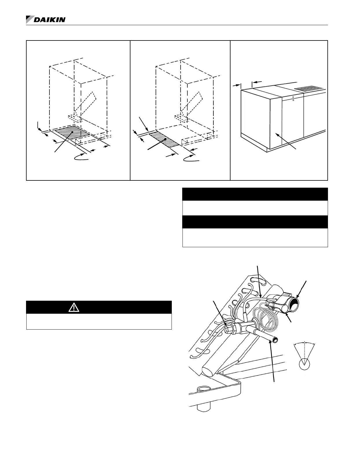
Figure 94: TXV Valve Piping Detail (Left Hand Shown)
Thermal Expansion
Valve (TXV)
Superheat Adjustment.
Return (Suction Line)
Bulb
attached in the 2 or
10 o'clock position
Equalization Tube
Supply (Liquid Line)
Remove Bulb When
Brazing To Prevent
Overheating Damage
Note: Install Pressure Taps on Supply (Liquid Line) and Return
(Suction Line) Piping (By Others).
Figure 93: Piping Stub-Up Details, 6″ End Panel
1-3/8" Left End
of unit
(Less end panel)
Piping Stub-up Within Cabinet
Unit End Compartment
Piping Stub-up Within 6" End Panel
End Panel 6"
Application and Dimension
Wall Line
1"
11
5
⁄
8
"
10"
Note: Space available in left
end compartment for piping
stub-up. Stub-up, including
unions and shutoff valves,
must disconnect below oor
line for unit installation and
removal.
Space available
at left end of unit
for piping stub-up
when 6" end panel
is used.
Left End of unit
(Less end panel)
Wall Line
4"
1"
Unit End Compartment
6"
6" End Panel