IM 817-7 20 www.DaikinApplied.com
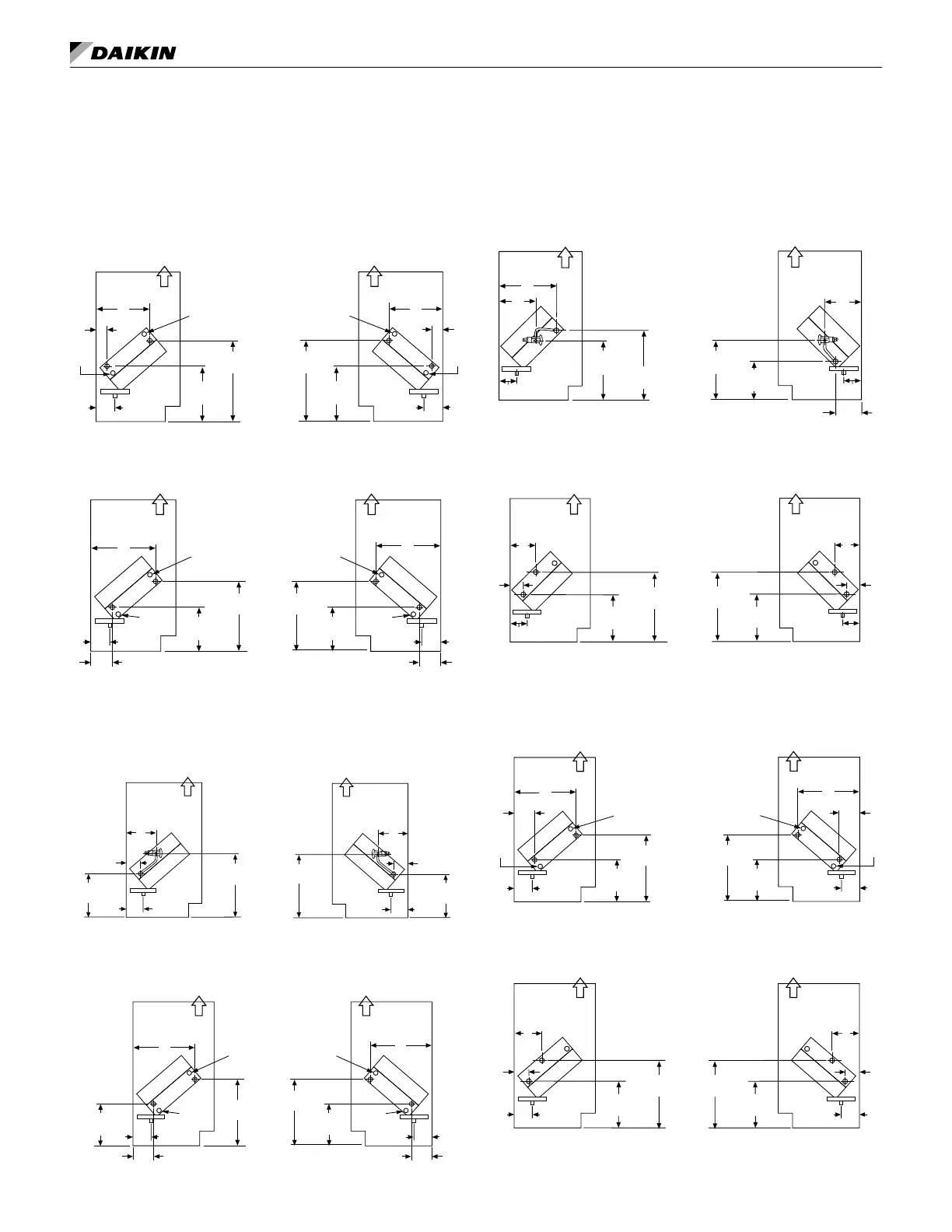
Coil Headers, Locations (continued)
Heat/Cool Units
Note: Numerical codes [#] denote optional stainless steel drain pan (cooling coils).
Chilled Water and Hot Water Unit
Figure 49: Chilled Water Cooling Coils V[5], S[6], W[7], Y[8]
Cooling (Left Hand)
16-1/8"
(410mm)
A
B
J
11"
(279mm)
Air Flow
CW
Vent
R
S
HW
Cooling (Right Hand)
16-1/8"
(410mm)
A
B
J
11"
(279mm)
Air Flow
CW
Vent
R
S
HW
Heating (Left Hand)
R
S
13-3/4"
(350mm)
A
B
J
8-1/2"
(216mm)
Air Flow
Vent
Plug
HW
CW
Heating (Right Hand)
R
S
13-3/4"
(350mm)
A
B
J
Air Flow
Vent
Plug
HW
CW
8-1/2"
(216mm)
Figure 50: Hot Water Heating Coils 65, 66, 67
Cooling (Left Hand)
16-1/8"
(410mm)
A
B
J
11"
(279mm)
Air Flow
CW
Vent
Plug
R
S
HW
Cooling (Right Hand)
16-1/8"
(410mm)
A
B
J
11"
(279mm)
Air Flow
CW
Vent
Plug
R
S
HW
Heating (Left Hand)
R
S
13-3/4"
(350mm)
A
B
J
8-1/2"
(216mm)
Air Flow
Vent
Plug
HW
CW
Heating (Right Hand)
R
S
13-3/4"
(350mm)
A
B
J
Air Flow
Vent
Plug
HW
CW
8-1/2"
(216mm)
Direct Expansion and Hot Water Unit
Figure 51: Direct Expansion Cooling Coils G[9]
Cooling (Left Hand)
DX
Cooling (Right Hand)
J
9-3/4"
Air Flow
HW
LL
SL
I
14-1/4"
(368mm)
DX
G
Heating (Left Hand)
R
S
13-3/4"
(350mm)
A
B
J
8-1/2"
(216mm)
Air Flow
Vent
Plug
HW
DX
Heating (Right Hand)
R
S
13-3/4"
(350mm)
A
B
J
Air Flow
Vent
Plug
HW
DX
8-1/2"
(216mm)
LL = Liquid Line
SL = Suction Line
HW
J
9-3/4"
Air Flow
LL
SL
I
14-1/4"
(368mm)
G
Figure 52: Hot Water Heating Coils 65, 66, 67
Cooling (Left Hand)
DX
Cooling (Right Hand)
J
9-3/4"
(248mm)
Air Flow
HW
LL
SL
I
14-1/4"
(368mm)
DX
G
Heating (Left Hand)
R
S
13-3/4"
(350mm)
A
B
J
8-1/2"
(216mm)
Air Flow
Vent
Plug
HW
DX
Heating (Right Hand)
R
S
13-3/4"
(350mm)
A
B
J
Air Flow
Vent
Plug
HW
DX
8-1/2"
(216mm)
LL = Liquid Line
SL = Suction Line
HW
J
9-3/4"
(248mm)
Air Flow
LL
SL
I
14-1/4"
(368mm)
G
S = Supply
R = Return
Direct Expansion and Steam Unit
Note: For opposite end drain steam coils (code 78, 79)
Return (R) is 7¼” (184mm) from bottom of unit and
(H) 2” (51mm) from the back of unit. Unless otherwise
noted, LH and RH connections are the same.
Figure 53: Direct Expansion Cooling Coils G[9]
14-1/4"
(368mm)
J
10-1/8"
(257mm)
R
S
H
K
Air Flow
14-1/4"
(368mm)
J
R
S
H
K
10-1/8"
(257mm)
Air Flow
Heating (Left Hand) Heating (Right Hand)
LL
SL
J
D
7-1/4"
(184mm)
Air Flow
11-3/4"
(299mm)
LL
SL
J
B
Air Flow
Cooling (Left Hand) Cooling (Right Hand)
13-3/4"
(349mm)
11-3/4"
(299mm)
D
LL = Liquid Line
SL = Suction Line
Steam
Steam
Figure 54: Steam Heating Coils 68, 69, 78, 79
14-1/4"
(368mm)
J
10-1/8"
(257mm)
R
S
H
K
Air Flow
14-1/4"
(368mm)
J
R
S
K
10-1/8"
(257mm)
Air Flow
Heating (Left Hand) Heating (Right Hand)
LL
SL
J
D
C
7-1/4"
(184mm)
Air Flow
11-3/4"
(299mm)
LL
SL
J
B
Air Flow
Cooling (Left Hand) Cooling (Right Hand)
13-3/4"
(349mm)
11-3/4"
(299mm)
D
LL = Liquid Line
SL = Suction Line
DX
DX
S = Supply
R = Return
Chilled Water and Steam Unit
Figure 55: Chilled Water Cooling Coils V[5], S[6]
14-1/4"
(368mm)
10-1/8"
(257mm)
R
S
H
K
Heating (Left Hand) Heating (Right Hand)
Cooling (Left Hand)
R
S
13-3/4"
(350mm)
A
B
J
8-1/2"
(216mm)
Air Flow
Vent
CW
Cooling (Right Hand)
R
S
13-3/4"
(350mm)
A
B
J
8-1/2"
(216mm)
Air Flow
Vent
CW
Steam
Steam
J
Air Flow
CW
J
Air Flow
CW
14-1/4"
(368mm)
R
S
H
K
10-1/8"
(257mm)
Figure 56: Steam Heating Coils 68, 69, 78, 79
14-1/4"
(368mm)
10-1/8"
(257mm)
R
S
H
K
Heating (Left Hand) Heating (Right Hand)
Cooling (Left Hand)
R
S
13-3/4"
(350mm)
A
B
J
8-1/2"
(216mm)
Air Flow
Vent
Plug
CW
Cooling (Right Hand)
R
S
13-3/4"
(350mm)
A
B
J
8-1/2"
(216mm)
Air Flow
Vent
Plug
CW
Steam
Steam
J
Air Flow
CW
J
Air Flow
CW
14-1/4"
(368mm)
R
S
H
K
10-1/8"
(257mm)