www.DaikinApplied.com 21 IM 817-7
Chilled Water and Electric Heating Coils
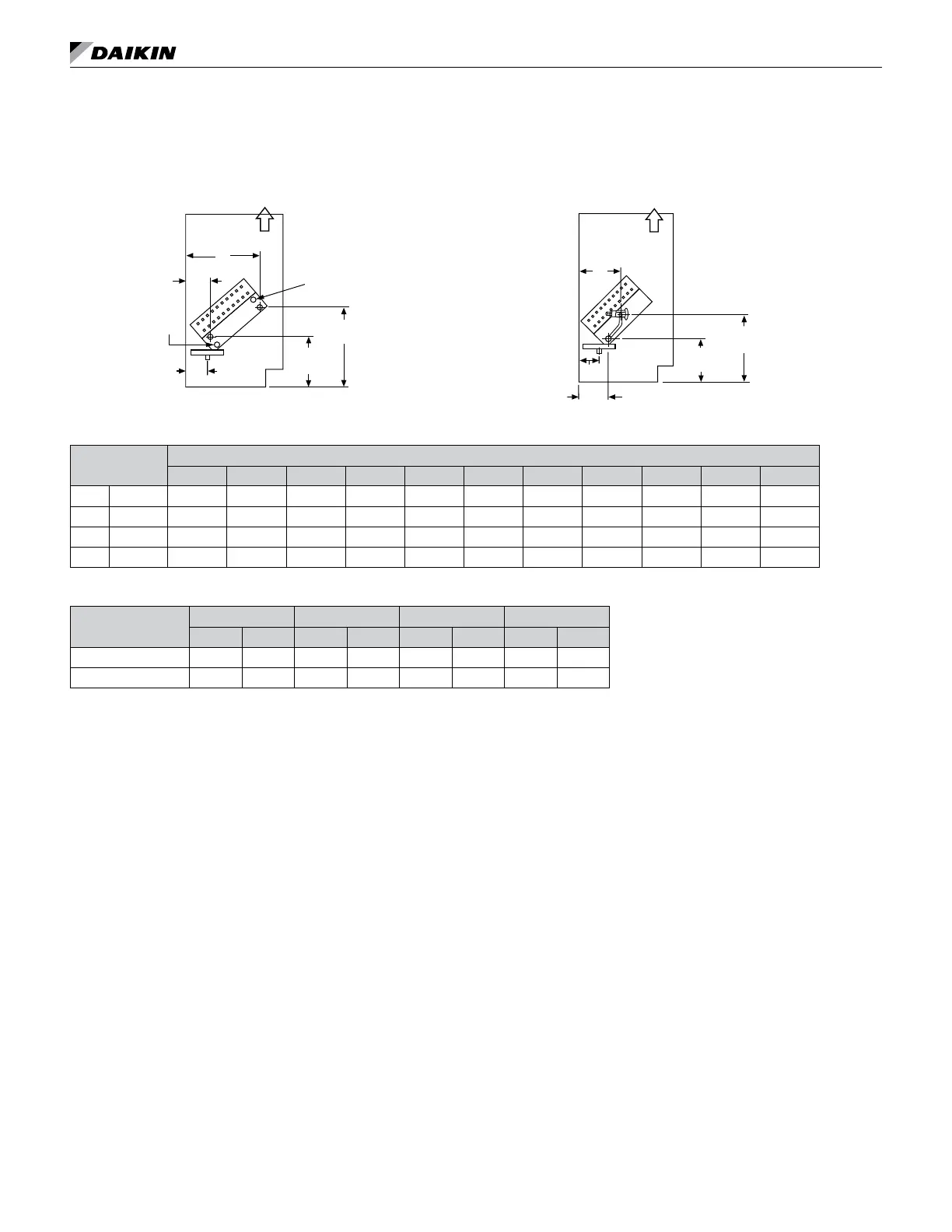
Figure 57: Chilled Water (1st Position) and Electric Heating
(Cooling Coils V[5], S[6], W[7]), (Heating Coils 12, 13)
R
S
13-3/4"
(350mm)
A
B
J
8-1/2"
(216mm)
Air Flow
Vent
CW
Direct Expansion and Electric Heating Unit
Figure 58: Direct Expansion (1st Position) and Electric
Heating (Cooling Coils G[9]), (Heating Coils 12, 13)
LL = Liquid Line
SL = Suction Lin
LL
SL
J
D
C
7-1/4"
(184mm)
Air Flow
11-3/4"
(299mm)
Table 6: Coil Connection Dimensions For Lettered Values
1
Unit Depth
Dimensions
A B C D E F G H I J K
in. 16-5/8 3-3/4 12-1/4 4-7/8 7-3/4 1-5/8 10-1/8 2-3/4 2-7/8 5-5/8 3 5
mm 422 95 311 124 198 41 257 70 73 143 76 127
in. 21-7/8 9 17-1/2 10-1/8 13 6-7/8 15-3/8 8 8-1/8 10-7/8 8-1/4 10-1/4
mm 556 229 445 257 330 175 391 203 206 276 210 260
Table 7: Direct Expansion (DX) Coil G[9] Connection Tubing
Unit Series
07 10 13 15
in mm in mm in mm in mm
Suction Line OD: 3/4 19 3/4 19 7/8 22 7/8 22
Liquid LIne OD: 1/4 6.35 1/4 6 3/8 10 3/8 10
 Loading...


