www.DaikinApplied.com 29 IM 817-7
Steam Modulating Valve Selection
The steam modulating control valve is expected to vary
the quantity of steam through the coil. Any movement
of the valve stem should produce some change in the
steam ow rate. To select a modulating steam valve:
1. Obtain the supply steam inlet pressure.
2. Determine the actual heat requirement of the space
to be heated.
Table 28: Modulating 2-Way, Normally Open, Steam Valves – Pressure Drop
Pressure Drop Across the Valve
2-Way CCV Part
No.
Cv
Maximum
Rating
Connection
Size
2 PSI 3 PSI 4 PSI 5 PSI 10 PSI 15 PSI
B215HT073 0.73
1/2"
10.99 13.71 16.11 18.33 28.03 36.74
B215HT186 1.86 22.34 34.93 41.06 46.70 71.42 93.60
B215HT455 4.55
54.65 85.44 100.43 114.24 174.72 228.97
B220HT731 7.31
3/4 inch 110.02 137.27 161.36 183.54 280.70 367.86
2-Way and 3-Way Hot Water and
Chilled Water Modulating Valve
Selection
The unit ventilator control valve is expected to be able
to vary the quantity of water that ows through the coil in
a modulating fashion. Any movement of the valve stem
should produce some change in the amount of water that
ows through the coil. Oversized control valves cannot do
this. For example, assume that when the control valve is
fully open, the pressure drop through the coil is twice as
great as the drop through the valve. In this case, the control
valve must travel to approximately 50% closed before it
can begin to have any inuence on the water ow through
the coil. The control system, no matter how sophisticated,
cannot overcome this. Oversized control valves can also
result in “hunting” which will shorten the life of the valve and
actuator and possibly damage the coil.
To correctly select the proper Chilled Water Modulating
Valve:
1. Determine the ow of water and the corresponding
pressure drop through the coil.
2. Obtain the pressure difference between the supply
and return mains.
3. Select a valve size (Cv) from Table 28, on the basis
of taking 50% of the available pressure difference (at
design ow) between the supply and return mains at
the valve location. The valve should have a pressure
drop greater than that of the coil.
Figure 76: Formula Equation to Calculate Cv
Q = Capacity in gallons per minute
Cv = Valve sizing coefcient determied experimentally
for each syle and size of valve, using water at
standard conditions as the test uid
∆P = Pressure differential in psi
G = Specic gravity of uid (water at 60°F = 1.0000)
Cv = Q
�
G
∆P
CAUTION
Care must be taken with modulating valves to provide proper
water ow. In freezing conditions, water ow must be maintained
through the heating coil or a suitable freeze-prevention solution
employed to prevent freeze-up. Similarly, the cooling coil must be
drained or a suitable freeze-prevention solution employed.
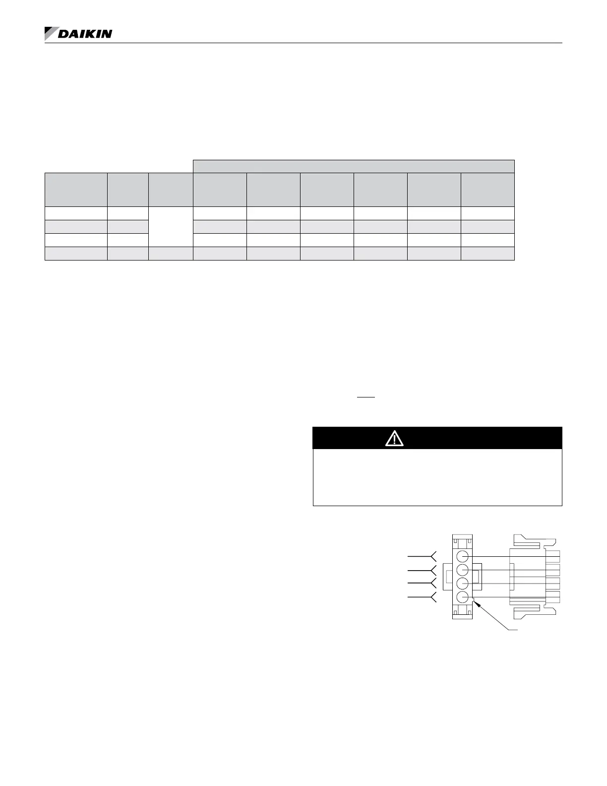
Figure 77: Actuator Wiring
WHT (Input 2 to 10 VDC)
RED (24VAC Supply)
(Output 2 to 10 VDC)
BLK (Common)
BLK
WHT
ORG
RED
Note: The actuator spring returns the valve to the open
position when the actuator is de-energized (off)