IM 817-7 28 www.DaikinApplied.com
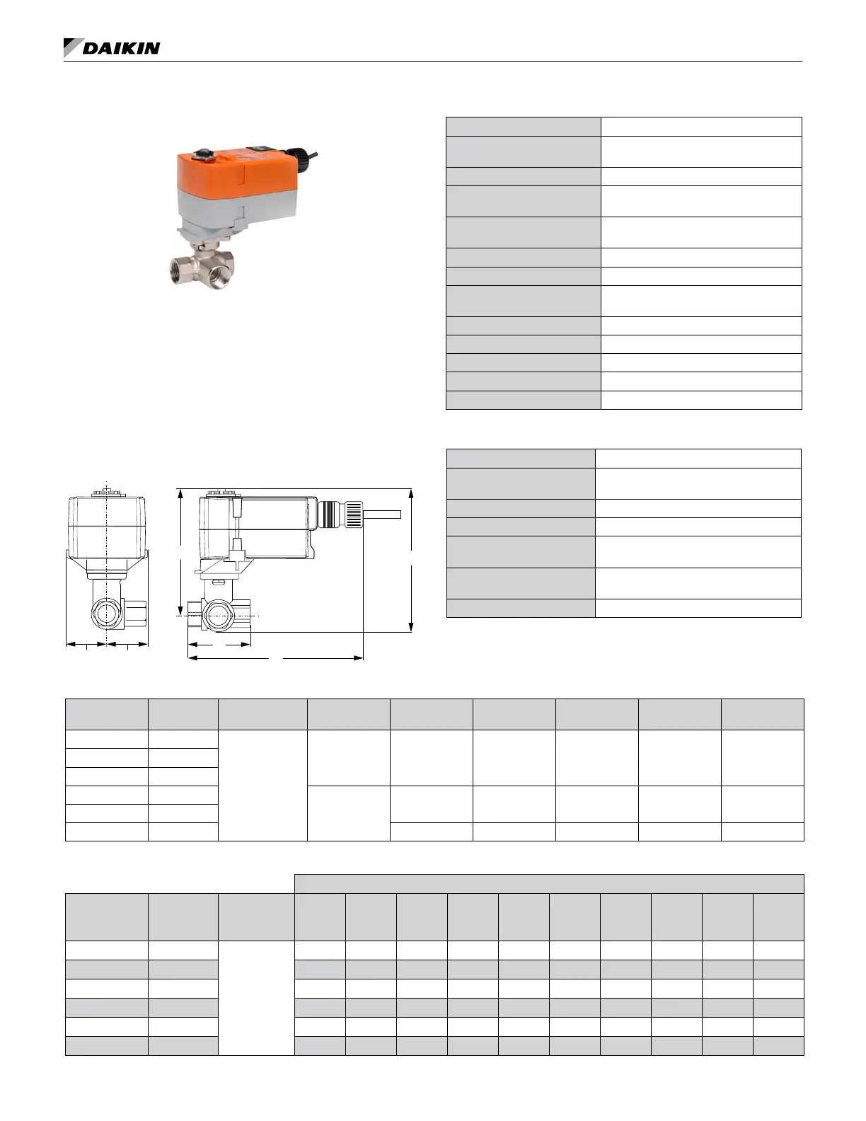
3-Way Modulating Valve (Chilled Water, Hot
Water or Combination)
Three-way modulating control valves for MicroTech are
designed to regulate the ow of hot or chilled water or
the combination. They consist of a nickel plated brass
body and stem with chrome plated brass ball valve, with
a spring return, proportional actuator. The optional valve
accessory is shipped separate from the unit ventilator
for eld installation to prevent shipping damage and to
provide exibility in making the eld piping connection.
Figure 75: 3-Way Modulating Valve (Chilled Water, Hot
Water or Combination) Dimensions
B
A
C
D
E F
AB
A
Table 24: 3-Way Actuator Specifications (CW, HW, CW/HW)
Power Supply 24 VAC, ±20%, 50/60 Hz, 24 VDC, ±10%
Electrical Connection
3ft [1m], 18 GA plenum cable with 1/2"
conduit connector
Overload Protection electronic throughout 0° to 95° rotation
Operating Range Y
2 to 10 VDC, 4 to 20 mA w/ ZG-R01 (500
Ω, 1/4 W resistor)
Input Impedance
100 k Ω for 2 to 10 VDC (0.1 mA), 500 Ω
for 4 to 20 mA
Feedback Output U 2 to 10 VDC, 0.5 mA max
Angle of Rotation Max. 95°, 90°
Position Indication
visual indicator, 0° to 95° (0° is full spring
return position)
Running Time (Motor) 95 sec
Running Time (Fail-Safe) <25 sec
Ambient Humidity max. 95% RH non-condensing
Ambient Temperature Range -22°F to 122°F [-30°C to 50°C]
Storage Temperature Range -40°F to 176°F [-40°C to 80°C]
Table 25: 3-Way Valve Body Specifications (CW, HW, CW/HW)
Service chilled, hot water, up to 60% glycol
Flow Characteristic
A-port Equal percentage; B-port modied
linear for constant ow
Controllable Flow Range 75°
Body Pressure Rating [psi] 600
Media Temperature Range
(Water)
0°F to 250°F [-18°C to 120°C]
Max Differential Pressure
(Water)
50 psi (345 kPa)
Close-Off Pressure 200 psi
Table 26: 3-Way Modulating Valve 1/2″ – Dimensions
Valve Part No. Cv
Connection Size
(inches)
A B C D E F
B309(B) 0.8
1/2"
6.59" (167mm) 2.38" (60mm) 4.9" (124mm) 4.32" (110mm) 1.53" (38mm) 1.2" (31mm)B310(B) 1.2
B311(B) 1.9
B312(B) 3.0
6.59" (167mm)
2.38" (60mm) 4.9" (124mm) 4.71" (120mm) 1.53" (38mm) 1.29" (33mm)
B313(B) 4.7
B318(B) 7.4 2.73" (69mm) 5.5" (140mm) 4.8" (122mm) 1.53" (38mm) 1.47" (37mm)
Table 27: Modulating 3-Way Hot Water, Chilled Water or 2-Pipe CW/HW Valve 1/2″ – Pressure Drop
Pressure Drop Across the Valve
3-Way CCV Part
No.
Cv
Maximum
Rating
Connection
Size
1 PSI 2 PSI 3 PSI 4 PSI 5 PSI 6 PSI 7 PSI 8 PSI 9 PSI 10 PSI
B309(B) 0.8
1/2"
0.8 1. 1.4 1.6 1.8 2.0 2. 2.3 2.4 2.5
B310(B) 1.2 1.2 1.7 2. 2.4 2.8 2.9 3.2 3.4 3.6 3.8
B311(B) 1.9 1.9 2.7 3.3 3.8 4.2 4.7 5.0 5.4 5.7 6.0
B312(B) 3.0 3.0 4.2 5.2 6.0 6.8 7.3 7.9 8.5 9.0 9.5
B313(B) 4.7 4.7 6.6 8.1 9.4 11 12 12 13 14 15
B318(B) 7.4
7.4 10 13 15 17 18 20 21 22 23